High-PFC constant current control device without loop compensation and voltage converter

A technology of constant current control and loop compensation, applied in the direction of high-efficiency power electronic conversion, output power conversion device, conversion of DC power input to DC power output, etc. Low problems, to achieve the effect of saving cost and space, system stability, and reducing peripheral components

Active Publication Date: 2014-10-29
SI EN TECH XIAMEN
View PDF5 Cites 7 Cited by
  • Summary
  • Abstract
  • Description
  • Claims
  • Application Information

AI Technical Summary

Problems solved by technology

[0006] The drive circuit has a rectifier module, an input capacitor Cin, a primary side voltage sampling network R1, R2, a transformer T, a power switch tube Q1, a primary side current sensing resistor R0, a secondary side rectifier diode D1, an output capacitor Cout, an output LED load L, Auxiliary winding side rectifier diode D2, auxiliary winding voltage sampling network R3, R4; the constant current PFC controller is provided with a separate compensation pin, which can be used to connect an external compensation capacitor Ccomp, which needs to be adjusted under different application conditions The capacitance of the compensation capacitor Ccomp is used to achieve system stability; of course, there are individual designs that do not require loop compensation through clever control methods, but due to their specific control methods, their versatility is reduced
[0007] In addition to the difference in loop compensation, there are two methods on the market to achieve high PFC constant current systems. The design of the two-stage control method is relatively simple, but the efficiency is low; the design of the single-stage control method is more complicated. , but more efficient

Method used


Image

  • High-PFC constant current control device without loop compensation and voltage converter
  • High-PFC constant current control device without loop compensation and voltage converter
  • High-PFC constant current control device without loop compensation and voltage converter

Examples


Embodiment Construction

[0038] In order to further explain the technical solution of the present invention, the present invention will be described in detail below through specific examples.

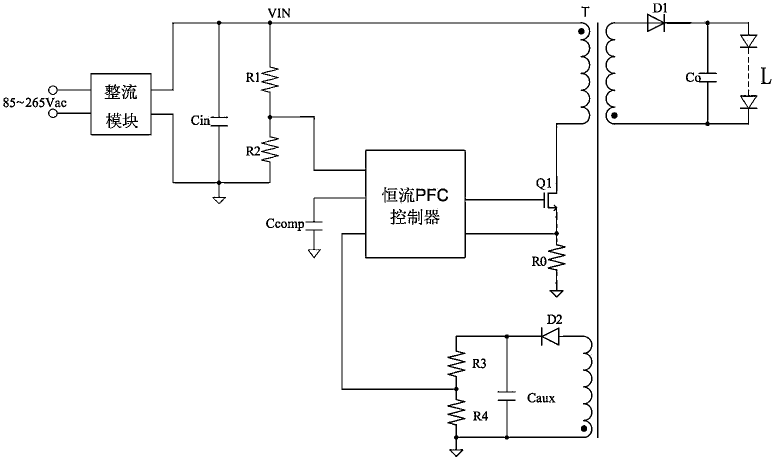
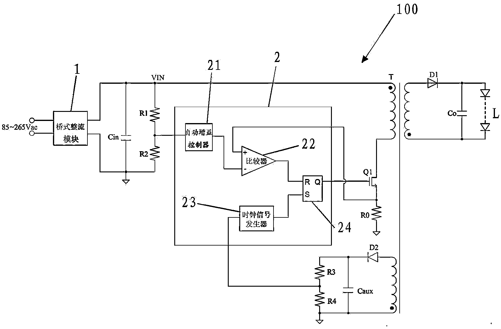
[0039] like figure 2 As shown, it is a schematic diagram of the application of a high PFC constant current control device 2 without loop compensation in the flyback converter 100 according to the present invention. The flyback converter 100 includes a bridge rectifier module 1, an input capacitor Cin, transformer T, power switch tube Q1, primary current sense resistor R0, primary voltage sampling resistor network R1, R2, secondary rectifier diode D1, output capacitor Cout, output LED load, auxiliary winding side rectifier diode D2, auxiliary winding Voltage sampling network R3, R4, Caux.

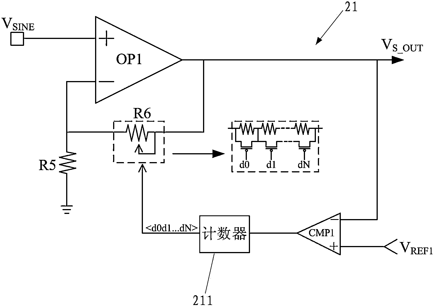
[0040] The high PFC constant current control device 2 without loop compensation involved in the present invention includes an automatic gain controller 21 , a peak current control comparator 22 , a clock signal generator 23 a...


PUM


Abstract

The invention discloses a high-PFC constant current control device without loop compensation and a voltage converter. The device comprises an automatic gain controller, of which the input end is an AC input voltage sampling signal of a primary side voltage sampling network, and the output end outputs a signal which is the same and of the same frequency with the input voltage but constant in amplitude; a peak current control comparator which has positive and negative input ends and output ends, wherein the negative input end is connected with the output end of the automatic gain controller, and the positive input end is connected with the positive end of a primary side current sensor resistor; a clock signal generator, of which the input end is a DC voltage sampling signal of an auxiliary winding voltage sampling network and the output end outputs a clock signal, the frequency of which is in direct proportion to a DC sampling voltage; and a trigger which is used for receiving the clock signal and a comparison signal output by a peak circuit control comparator and controlling the connection or disconnection of a power switch tube based on the clock signal and the comparison signal. The constant current control device can realize high PFC and output constant-current control without light coupling and loop compensation.

Description

technical field [0001] The present invention relates to the technical field of switching power supplies, and more specifically relates to a high PFC constant current control device without loop compensation, which can be applied to isolated flyback converters, non-isolated buck-boost converters and non-isolated buck-boost converters at the same time. isolated buck converter. Background technique [0002] The light characteristics of LEDs are usually described as a function of current rather than voltage. A small change in the forward voltage of the LED will cause a large change in the LED current, which will cause a large change in the current. Therefore, using a constant voltage source to drive cannot guarantee the consistency of the LED brightness, and affects the reliability, life and light decay of the LED. Therefore, LEDs are usually driven by a constant current source. [0003] For safety reasons, many LED lamps require the LED driver to have an isolation function, t...

Claims


Application Information

Patent Timeline
Patent Type & Authority Applications(China)
IPC IPC(8): H02M1/42H02M3/335
CPCY02B70/10
Inventor 吴超郑鹏峰
Owner SI EN TECH XIAMEN
Why Eureka
Try Eureka