
Machining process technique for aluminum alloy control plane

A technology of mechanical processing and process methods, which is applied to projectiles, offensive equipment, weapon types, etc., can solve the problems of low processing efficiency, increased production costs and time, and difficulty in guaranteeing the quality of parts, and achieves high-quality, high-efficiency and low-cost processing. , Eliminate cost and time, the effect of parts quality assurance

Active Publication Date: 2014-11-05
BEIJING HANGTIAN XINFENG MECHANICAL EQUIP
View PDF6 Cites 9 Cited by
  • Summary
  • Abstract
  • Description
  • Claims
  • Application Information

AI Technical Summary

Problems solved by technology

This process requires at least 10 processes including two heat treatments. The disadvantages are: the process is long, and the ordinary low-speed milling process needs to be turned over repeatedly to control deformation. The heat treatment process increases production costs and time, and the boring process It takes a long time and it is difficult to process deep holes with a depth-to-diameter ratio greater than 10 times. Milling and removing chucks can easily cause deformation of parts, etc. The processing efficiency of this process is low and the quality of parts is difficult to guarantee.

Method used


Image

  • Machining process technique for aluminum alloy control plane
  • Machining process technique for aluminum alloy control plane
  • Machining process technique for aluminum alloy control plane

Examples


Embodiment Construction

[0015] A folding rudder has a length of 300mm, a width of 150mm, a maximum thickness of 25mm, a hypotenuse angle of 45°, a slot length of 50mm, a width of 30mm, and the diameter of the through hole on the central plane of symmetrical thickness The distance from the long side is 15mm, and the symmetry of the profile is required to be 0.1mm; the specific process method is as follows:

[0016] Preparation before processing, after quenching the aluminum alloy plate 7A09, apply a permanent tensile plastic deformation of 1% to 3% along the rolling direction, and blank the plate to a size of 310mm×180mm×35mm;

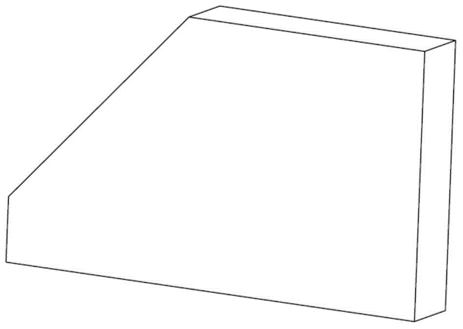
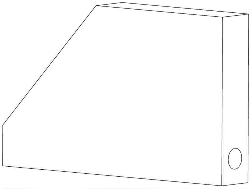
[0017] The first step, the thickness and shape of the fine milling chuck: on ordinary milling machines Face milling cutter milling thickness to use The peripheral shape of the end mill is 300mm long, 170mm wide, and the bevel angle is 45°. The groove is not processed, and the part structure after processing is as follows figure 2 shown;

[0018] The second step, gun d...


PUM


Abstract

The invention provides a machining process technique for an aluminum alloy control plane. The machining process technique comprises the following steps of preparation before machining, pre-stretching on aluminum alloy plates, finish milling on the thickness and the appearance of a chuck, machining on deep holes by using a gun drill, high-speed finish milling on profiles and chuck removal by linear cutting machining. The plates are pre-stretched, the original inner stress generated in a raw material forming process is reduced, and deformation of parts in the followed-up machining process is reduced; a boring procedure is replaced by using an outward chip removal deep hole gun drill, the machining time is effectively reduced, and deep holes of which the depth-diameter ratio is greater than the gun drill by 10 times can be machined; machining stress caused by cutting force in a milling machining process and deformation caused by cutting heat can be reduced by high-speed milling machining, and cost and time on heat treatment production are avoided; and a chuck is removed by linear cutting instead of milling machining, the machining stress is further reduced, and the deformation of the parts is controlled. The problems that the machining efficiency in the existing machining technology is low, and the quality of parts is difficult to guarantee are solved. High-quality, high-efficiency and low-cost machining on control planes and parts such as missile wings can be realized.

Description

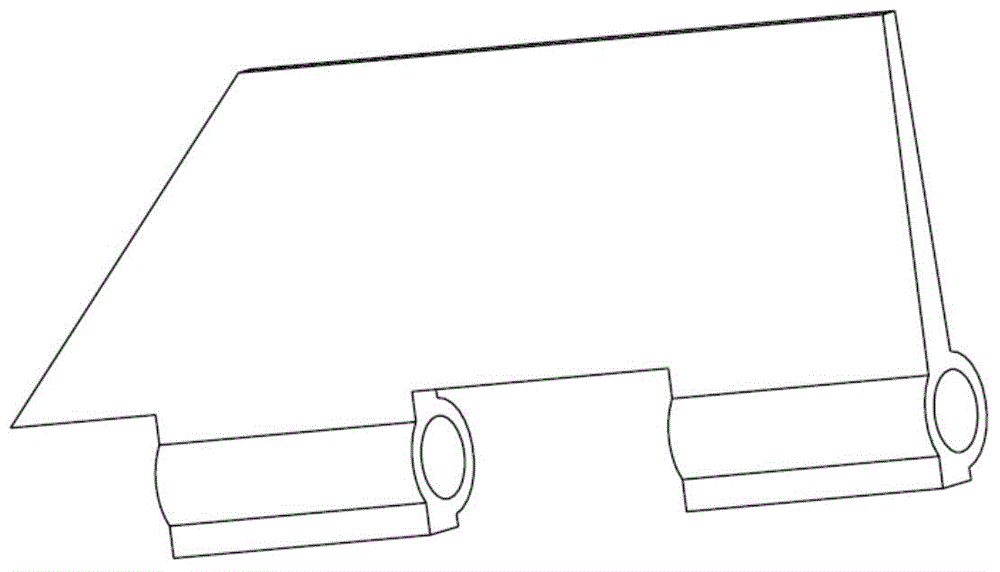
technical field [0001] The invention relates to an aluminum alloy machining method, in particular to an aluminum alloy rudder surface machining method. Background technique [0002] Folding the rudder / wing can reduce the structural weight, reduce the structural size, and improve the maneuverability of the missile. It is widely used in tactical missiles and cruise missiles. This type of rudder surface / wing generally adopts an aluminum alloy sheet structure with multiple surfaces and a folding hole in the center surface, such as figure 1 shown. It is not easy to clamp during part processing, the partial material removal allowance is large, it is easy to deform, the symmetry of the profile is difficult to guarantee, the processing quality is difficult to control, and the production efficiency is also low. [0003] The traditional processing technology of folding rudder / wing generally chooses ordinary aluminum alloy plates 2A12 and 7A09. The process flow is generally: ① rough ...

Claims


Application Information

Patent Timeline
IPC IPC(8): B23P15/00
CPCB23P15/00F42B10/04
Inventor 魏建中耿久全
Owner BEIJING HANGTIAN XINFENG MECHANICAL EQUIP
Learn More