Centrifugal sleeve tube structure used for separating and extracting DNA

A centrifuge sleeve and centrifuge tube technology, which is applied in the field of nucleic acid DNA or RNA separation and purification equipment, can solve the problems of not being able to reflect the good effect of filtering out impurities, difficult to control the loss of DNA templates, and unreasonable structures, etc., to achieve a simple structure , Good impurity removal effect, guarantee the effect of adsorption capacity

Active Publication Date: 2014-11-05
常熟市雷号医疗器械有限公司
View PDF6 Cites 4 Cited by
  • Summary
  • Abstract
  • Description
  • Claims
  • Application Information

AI Technical Summary

Problems solved by technology

For this reason, the applicant has searched the literature, and the Chinese patent authorization announcement number CN201744365U recommends a "filter membrane centrifuge tube". It can be seen from the description that there is no need to pipette during the operation, but due to the unreasonable structure, there are the following disadvantages: First, impurities are easy to enter the lower part of the centrifuge tube from the filter membrane (the patent is called a mixed fiber microporous filter membrane) with the body fluid, thus affecting the water-soluble The purity of the DNA template is affected; the second is that it is difficult to form an ideal seal between the rubber ring for the filter membrane and the inner wall of the centrifuge tube, so impurities will also enter from the micro-gap between the rubber ring and the inner wall of the centrifuge tube The lower part of the centrifuge tube, because the rubber ring taught by the patent must meet the requirements of being pluggable with the lumen wall of the centrifuge tube, so if in order to achieve the ultimate...

Method used


Image

  • Centrifugal sleeve tube structure used for separating and extracting DNA
  • Centrifugal sleeve tube structure used for separating and extracting DNA

Examples


Embodiment 1

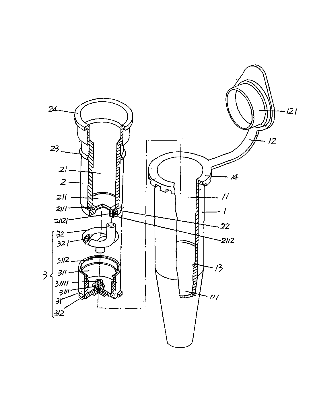
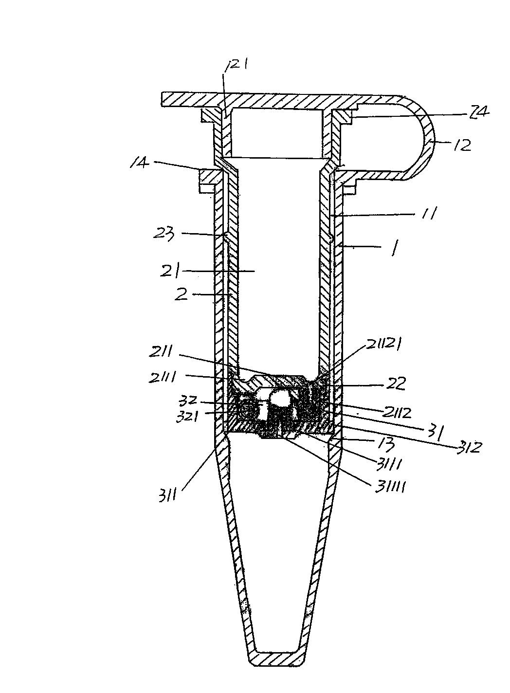
[0019] See figure 1 and figure 2 , provides a centrifuge tube 1, the centrifuge tube 1 is preferably molded using transparent plastic, on the cavity wall of the centrifuge tube cavity 11 of the centrifuge tube 1 and at the lower part of the height direction of the centrifuge tube cavity 11 to form a Narrow steps 13. As shown in the figure, the diameter of the lower part of the centrifuge tube lumen 11 is narrowed to form a liquid storage chamber 111, and the water-soluble DNA template after the impurity removal is stored by this liquid storage chamber 111, so that the silicon The beads are dropped in and adsorbed. A connection band 12 is formed at the opening of the centrifuge lumen 11 of the centrifuge tube 1 , and a plug cap 121 is connected to the end of the connection band 12 .

[0020] As a preferred solution, a centrifuge tube support flange 14 can also be formed on the outer wall of the centrifuge tube 1 and around the mouth corresponding to the centrifuge tube lume...


PUM


Abstract

A centrifugal sleeve tube structure used for separating and extracting DNA belongs to the field of equipment used for separation and purification of nucleic acid DNA or RNA. The structure includes a centrifugal tube. A connecting ribbon is formed on an upper part of the centrifugal tube. A plug cover is connected to an end of the connecting ribbon. An inner sleeve tube is disposed in a centrifugal tube chamber. A liquid discharge groove is formed on a bottom wall of an inner sleeve tube chamber and one side, which is opposite to the inner sleeve tube chamber, of the bottom wall is extended to form an inner sleeve connecting port. An impurity-filtering mechanism includes a transition sleeve cylinder and a coil. A transition sleeve cylinder matching joint is formed on a central position of the bottom of a transition sleeve cylinder chamber, wherein the center of the joint forms a liquid discharge hole. The coil is disposed in the transition sleeve cylinder chamber with one end being matched with the inner sleeve connecting port and the other end being matched with the transition sleeve cylinder matching joint. A coil chamber of the coil is filled with filtering materials. By means of the structure, a secondary pipetting process is unnecessary so that a water-soluble DNA template is free from losing; and an impurity-removing effect is excellent and a PRC amplification operation is ensured. The structure is convenient, quick to operate, is labor-saving, is good in the impurity-removing effect, is simple and is easy to manufacture.

Description

technical field [0001] The invention belongs to the technical field of equipment for separating and purifying nucleic acid DNA or RNA, and in particular relates to a centrifuge sleeve structure for separating and extracting DNA. Background technique [0002] Separation and purification, that is, extraction of DNA, has positive significance in the fields of medical treatment, criminal case investigation, identification of victims of various accidents such as traffic accidents, archaeology, and animal and plant inspection and quarantine. DNA detection methods are mainly but not important. It is limited to the following types: phenol-chloroform extraction method, chelex-100 method; magnetic bead method; organic solvent method; salting-out method and silica bead method, etc. However, no matter which method is used, its common characteristics or common requirements can be roughly summarized into the following two aspects: one is to maximize the yield and purity of DNA or RNA and ...

Claims


Application Information

Patent Timeline
IPC IPC(8): C12M1/24
CPCC12N15/1017
Inventor 周洪保
Owner 常熟市雷号医疗器械有限公司
Why Eureka
Try Eureka