
Thin film transistor, array substrate and display device

A technology of thin-film transistors and array substrates, applied in the field of thin-film transistors, can solve the problems of ion pollution and high cost, and achieve the effects of reducing production costs, small leakage current, and improving characteristics

Inactive Publication Date: 2014-11-05
BOE TECH GRP CO LTD +1
View PDF5 Cites 0 Cited by
  • Summary
  • Abstract
  • Description
  • Claims
  • Application Information

AI Technical Summary

Problems solved by technology

[0003] In view of this, the present invention provides a thin film transistor, an array substrate and a display device to solve the existing problem of using a lightly doped drain to suppress the leakage current of the thin film transistor, which easily leads to ion pollution and high cost

Method used


Image

  • Thin film transistor, array substrate and display device
  • Thin film transistor, array substrate and display device
  • Thin film transistor, array substrate and display device

Examples


Embodiment Construction

[0015] First, the realization principle of the thin film transistor of the embodiment of the present invention will be briefly described.

[0016] Thin film transistors usually include a gate electrode, a gate insulating layer, a semiconductor layer, a source electrode, and a drain electrode. When the thin film transistor is turned on, a voltage is applied to the gate electrode. The gate voltage generates an electric field in the gate insulating layer, and the power line is directed from the gate electrode to the semiconductor layer Surface, and induced charges on the surface. As the gate voltage increases, the surface of the semiconductor layer will change from a depletion layer to an electron accumulation layer, forming an inversion layer. When it reaches a strong inversion type (that is, when it reaches the turn-on voltage), a voltage will be applied between the source electrode and the drain electrode. Carriers pass through the conductive channel.

[0017] When the thin film t...


PUM


Abstract

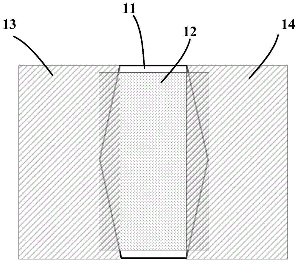
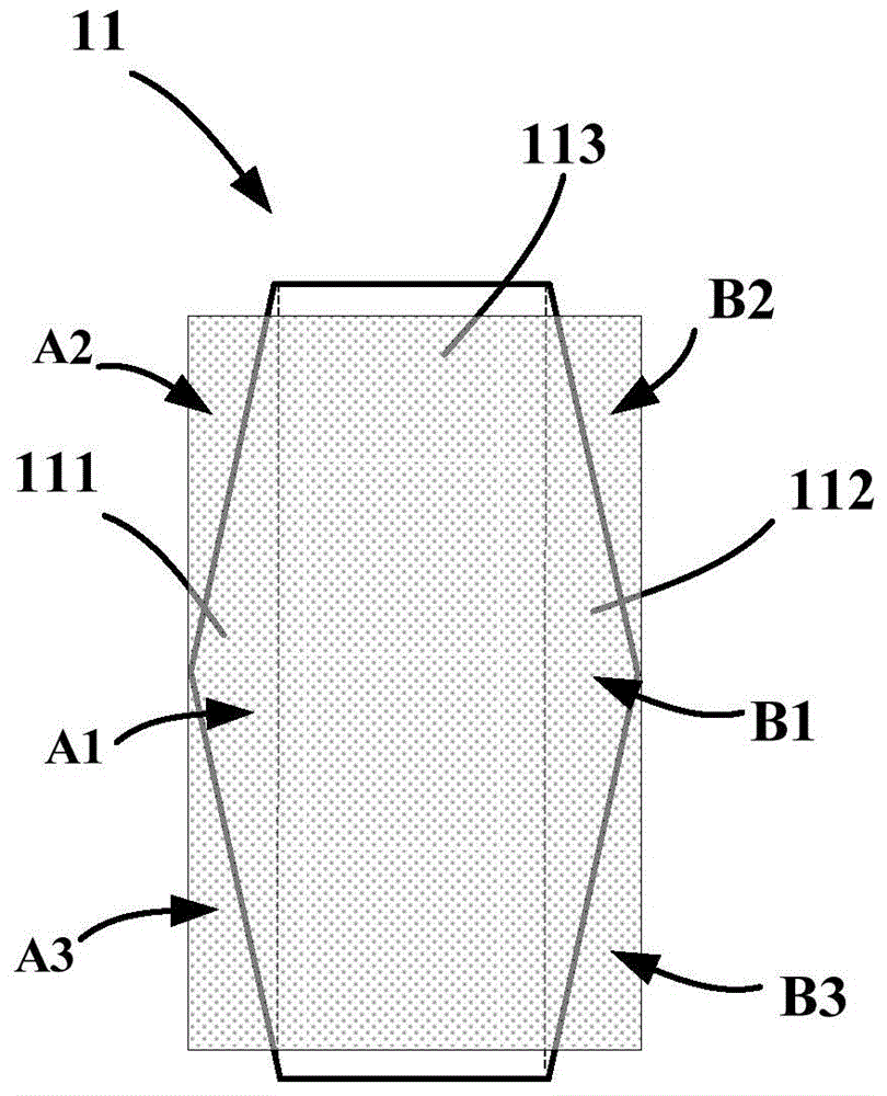
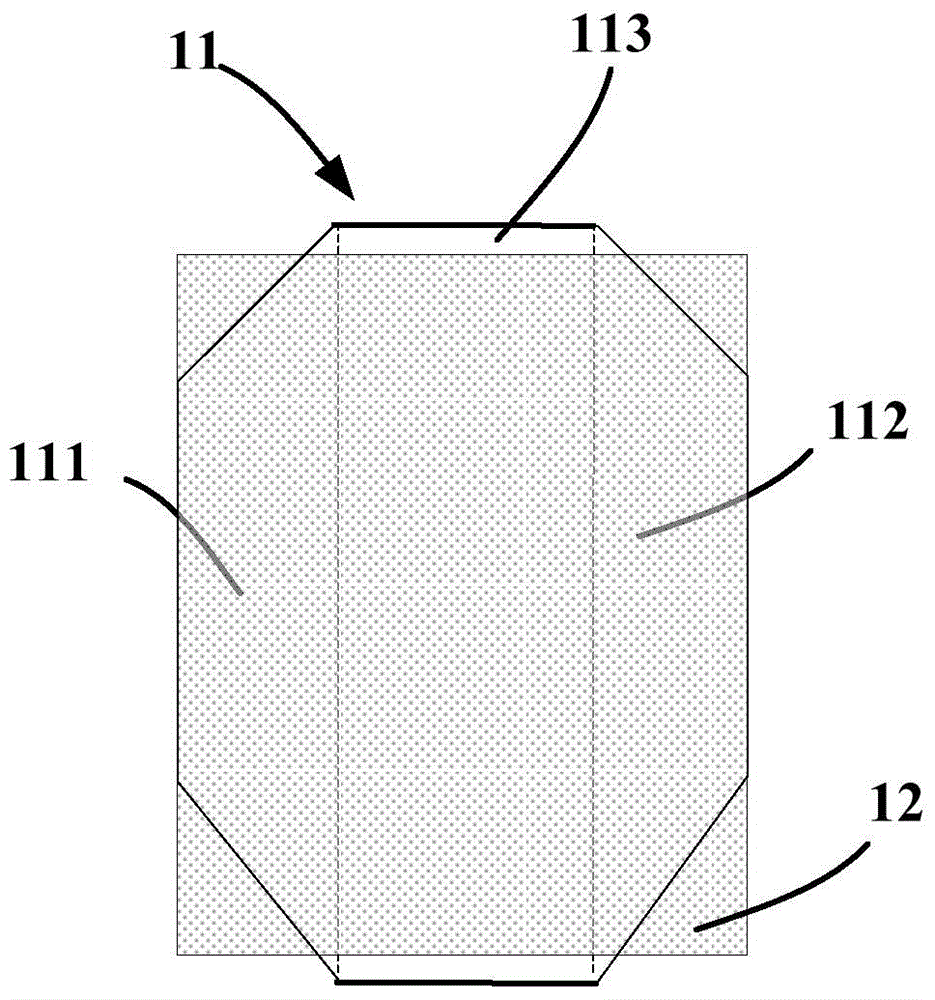
The invention provides a thin film transistor, an array substrate and a display device. The thin film transistor comprises a grid electrode, a grid insulation layer, a semiconductor layer, a source electrode and a drain electrode, wherein the grid electrode comprises a first region arranged at the side of the source electrode, a second region arranged at the side of the drain electrode side and an intermediate region arranged between the first region and the second region, the intermediate region completely covers the semiconductor layer arranged opposite to the intermediate region, and the first region or the second region covers a partial region of the semiconductor layer arranged opposite to the first region or the second region.

Description

Technical field [0001] The invention relates to the field of thin film transistors, in particular to a thin film transistor, an array substrate and a display device. Background technique [0002] In the LTPS (low temperature polysilicon) process, leakage current is one of the main reasons for the decrease in its yield. At present, in the LTPS TFT-LCD (thin film transistor liquid crystal display) process, the lightly doped drain method (LDD, Light Doped Drain) to suppress abnormally increased leakage current. This method requires ion doping, which can easily lead to ion contamination and lattice distortion. In addition, ion doping also increases the process and raw materials (such as photoresist and Doping ions, etc.), increasing production costs. Summary of the invention [0003] In view of this, the present invention provides a thin film transistor, an array substrate, and a display device to solve the problem that the existing method of using lightly doped drains to suppress th...

Claims


Application Information

Patent Timeline
Patent Type & Authority Applications(China)
IPC IPC(8): H01L29/786H01L27/12
CPCH01L29/41H01L29/786H01L27/1214H01L29/42356H01L29/42384
Inventor 韩帅张琨鹏高鹏飞王凤国白妮妮康峰刘宇
Owner BOE TECH GRP CO LTD
Learn More