Estimating system and method for fluid velocity

A fluid velocity and fluid technology, applied in the system field of estimating fluid velocity, can solve the problems of not being able to measure the blood flow velocity profile in blood vessels in real time, the blood velocity is not accurate enough, and the amount of calculation is large, so as to improve the signal-to-noise ratio and reliability , High calculation accuracy, high real-time effect

Inactive Publication Date: 2014-11-19
SHENZHEN INST OF ADVANCED TECH
View PDF3 Cites 14 Cited by
  • Summary
  • Abstract
  • Description
  • Claims
  • Application Information

AI Technical Summary

Problems solved by technology

[0008] The mixer, sample-and-hold and filter used in the traditional analog demodulation process will introduce additional noise, and the demodulator is only for a specific transducer and a given frequency range, which has poor flexibility
The existing technology equipment can only measure the velocity of the fixed sampling volume in the blood vessel. The blood flow velocity in the middle of the blood vessel is used to replace the blood flow velocity in the blood vessel. The measured blood velocity is not accurate enough, and the blood flow in the blood vessel cannot be measured in real time. velocity profile
If the intravascular velocity profile is to be obtained, it is usually based on the flow velocity in the middle of the blood vessel through a time-domain correlation algorithm to make assumptions about the blood flow velocity profile. The parabolic shape is used for peripheral blood vessels, and the blunt shape is used for high-velocity vessels such as the aortic arch. The calculation of the velocity profile is not only complicated and computationally intensive, but also not a true reflection of the blood flow in the blood vessel

Method used


Image

  • Estimating system and method for fluid velocity
  • Estimating system and method for fluid velocity
  • Estimating system and method for fluid velocity

Examples


Embodiment 1

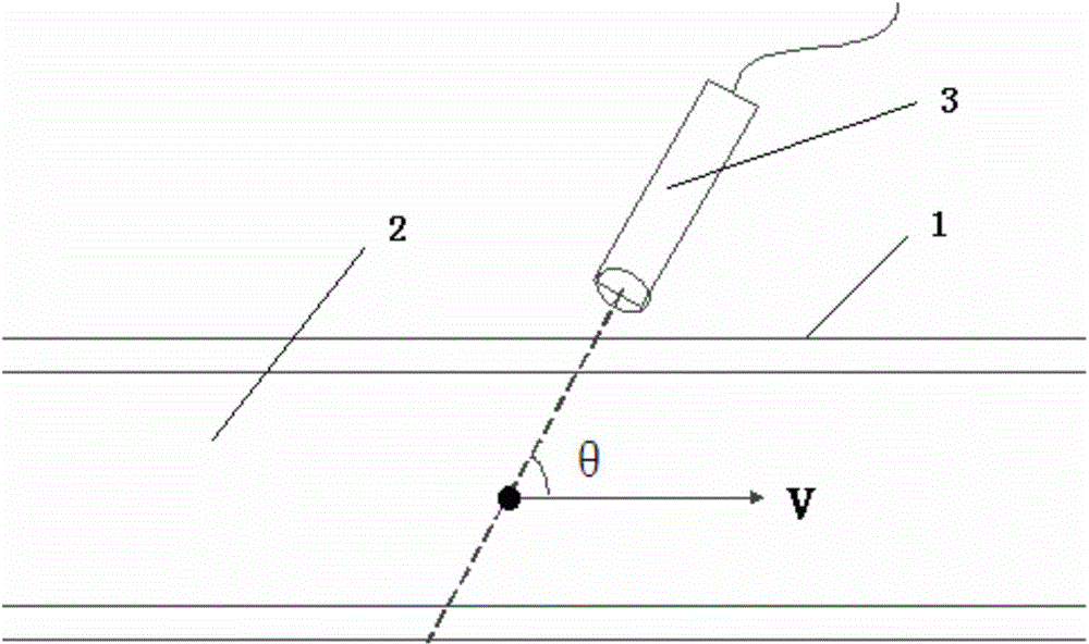
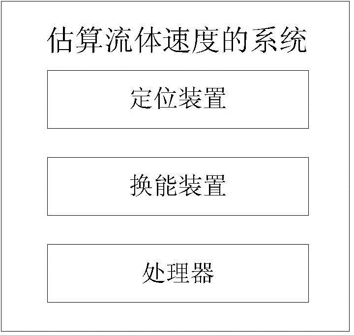
[0049] Such as Figure 3 to Figure 7 As shown, the system for estimating fluid velocity of the present application, an embodiment thereof, includes a positioning device, a transducer device and a processor. The positioning device is used to determine the position of the fluid to be detected by ultrasonic imaging, determine the velocity profile to be detected, and select a plurality of signal sampling points on the profile. The transducer device includes a transducer, and the transducer is used to transmit ultrasonic waves to the fluid and receive pulse echo signals under the control of the processor, Figure 4A schematic diagram of selecting multiple signal sampling points is shown, wherein 1 is a blood vessel wall, 2 is blood in a blood vessel, and 3 is an ultrasonic transducer. The processor is also used to process the pulse echo signal, calculate the fluid velocity of multiple signal sampling points, and perform curve fitting on the fluid velocity values ​​of multiple sign...

Embodiment 2

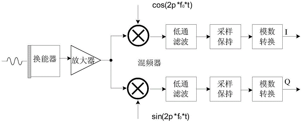
[0056] Embodiment 2 is a specific application example of the present application. Such as Figure 5 As shown, the system for estimating fluid velocity of the present application is mainly divided into two parts: an ultrasonic transducer and a signal processing unit. The signal processing unit is connected with the computer. The ultrasonic transducer mainly completes the conversion between the excitation electrical signal and the ultrasonic signal. The signal processing unit mainly completes the control of the ultrasonic modulation excitation signal and the processing of the ultrasonic echo signal. FPGA is a programmable processor in the system. It will complete the modulation pulse signal excitation control, echo signal acquisition control, real-time signal processing control and signal transmission control. The computer completes the command control and image display and processing of the system. The system of the present application can simultaneously measure the blood ...

Embodiment approach

[0061] Such as Figure 8 As shown, the method for estimating fluid velocity of the present application, an implementation thereof, comprises the following steps:

[0062] Step 802: Determine the position of the fluid to be detected by ultrasonic imaging, determine the velocity profile to be detected, and select multiple signal sampling points on the profile. In one embodiment, the fluid comprises blood flowing in a blood vessel. This application can be used to estimate blood flow velocity.

[0063] Step 804: Use the processor to send excitation pulses to the ultrasonic transducer, and the ultrasonic transducer sends ultrasonic waves to the fluid and receives pulse echo signals. In one embodiment, the processor includes an FPGA or an ARM processor.

[0064] Step 806: The processor processes the pulse echo signal to calculate the fluid velocity at multiple signal sampling points.

[0065] Step 808: Perform curve fitting on the fluid velocity values ​​of the plurality of sign...


PUM


Abstract

The invention discloses an estimating system and method for fluid velocity. The estimating system comprises a positioning device, a transducer and a processor. The positioning device is used for determining position of to-be-detected fluid through ultrasonic imagining and selecting a plurality of signal sampling sites on a determined section of to-be-detected velocity. The transducer is used for, under the control of the processor, sending ultrasonic to the fluid and receiving pulse echo signals. The processor is used for processing the pulse echo signals, calculating the fluid velocities of the signal sampling sites and performing curve fitting to fluid velocity values of the signal sampling sites to acquire a section curve of the fluid velocity. With the processor, such as FPGA (field-programmable gate array), blood flow velocities with different depth in blood vessels are simultaneously sampled and measured so as to achieve the blood flow velocities. In this way, abnormal blood flow is timely reflected, and signal processing timeliness and calculation accuracy are higher, so that diagnostic basis is provided for diagnosis of vascular diseases.

Description

technical field [0001] The present application relates to medical ultrasound imaging technology, and in particular to a system and method for estimating fluid velocity. Background technique [0002] Medical ultrasound imaging technology is an imaging technology based on ultrasound. With the rapid development of medicine, materials, computers, electronic engineering and other technologies, the performance of medical ultrasound imaging equipment has been continuously improved, its functions have been continuously improved, and its uses have been continuously expanded. Ultrasound imaging diagnosis has the characteristics of high spatial resolution, real-time fast imaging, simple operation method, no contraindication, no damage, repeatable, portable and economical, and has been widely used in various medical applications. Together with CT and MRI, it constitutes an essential imaging diagnostic technique in clinical medicine. [0003] A large number of clinical studies have sho...

Claims


Application Information

Patent Timeline
Patent Type & Authority Applications(China)
IPC IPC(8): A61B8/06
Inventor 邱维宝叶宗英郑海荣
Owner SHENZHEN INST OF ADVANCED TECH
Why Eureka
Try Eureka