Transmission type pulse compression grating device and preparation method thereof

A pulse compression and transmission technology, applied in diffraction grating and other directions, can solve the problems of large deformation of the substrate, affecting the output laser aberration, substrate deformation, etc., to improve the utilization rate of laser light energy and improve the laser damage threshold.

Active Publication Date: 2014-11-19
SUZHOU UNIV
View PDF7 Cites 5 Cited by
  • Summary
  • Abstract
  • Description
  • Claims
  • Application Information

AI Technical Summary

Problems solved by technology

In addition, in order to reduce the adverse effects of the optical nonlinear effect produced in the bulk material under the strong laser field, the thickness of the transmission pulse compression grating substrate needs to be very thin, and the aspect ratio (device aperture to thickness ratio) is generally greater than 50, and the plated The anti-reflection coating is easy to cause the deformation of the substrate, resulting in the deterioration of the diffraction wavefront of the pulse compression grating
The larger the diameter-thickness ratio of the grating substrate, the more serious the deformation of the substrate caused by the coating, and the worse the corresponding diffraction wavefront
[0004] Reference Chun Zhou et al. "Wavefront analysis of high-efficiency, largescale, thin transmission gratings" Optics Express (2014), in order to reduce the optical nonlinear effect under the strong laser field, the base material of the transmission grating must be very thin, only 1mm , the grating aperture is 180mm, and the diameter-thickness ratio reaches 180. In this paper, the plated anti-reflection film is used to improve the utilization rate of light energy. Due to the stress of the plated anti-reflection film, the diameter-thickness ratio is too large, resulting in a large deformation of the substrate. Causes the grating diffraction wave surface to deteriorate, thus affecting the aberration of the output laser

Method used


Image

  • Transmission type pulse compression grating device and preparation method thereof
  • Transmission type pulse compression grating device and preparation method thereof
  • Transmission type pulse compression grating device and preparation method thereof

Examples


Embodiment 1

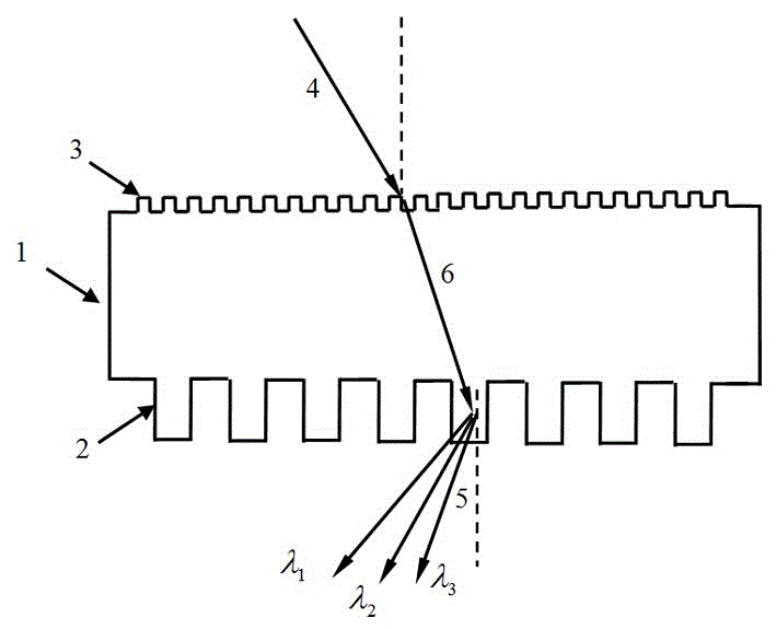
[0025] Embodiment one: see attached figure 2 As shown, a transmission pulse compression grating device includes a fused silica substrate 1, a transmission pulse compression grating microstructure 2 is arranged on one optical surface of the fused silica substrate 1, and on the other side of the fused silica substrate 1 A high-frequency anti-reflection grating microstructure 3 is arranged on an opposite optical surface. Its electron microscope photograph sees appendix Figure 5 And attached Image 6 shown.

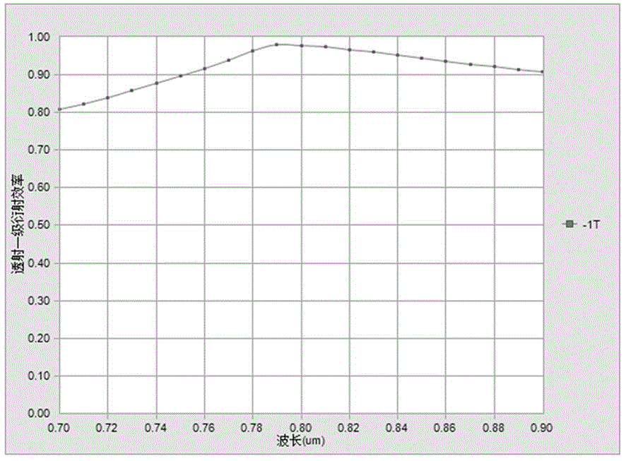
[0026] In this embodiment, the wavelength range of the pulse compression grating is 700nm-900nm, TE polarization, the center wavelength is 800nm, the incident angle of the beam is 30 degrees, the spatial frequency of the pulse compression grating is 1250line / mm, and the grating material is fused silica.

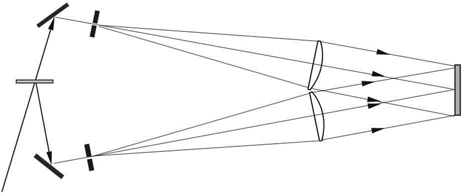
[0027] Such as figure 2 As shown, the incident laser beam 4 undergoes first-order dispersion transmission at the transmissive pulse compression grating 1 , and the fo...


PUM


Abstract

The invention discloses a transmission type pulse compression grating device and a preparation method thereof. The device comprises a fused silica substrate and a transmission type pulse compression grating arranged at one optical surface of the fused silica substrate. The transmission type pulse compression grating device is characterized in that the other opposite optical surface of the fused silica substrate is provided with a high-frequency antireflection grating micro structure. A method with the combination of holographic lithography and ion etching transfer is employed to realize the preparation of the device. According to the device and the method, the beam dispersion and antireflection can be realized at the same time through one device, the laser damage threshold and light energy utilization rate of the transmission type pulse compression grating are raised, and the device and the method have an important application value in the field of ultra-intense and ultrafast laser.

Description

technical field [0001] The invention relates to an optical element and a preparation method thereof, in particular to a high damage threshold transmissive pulse compression grating and a preparation method thereof. Background technique [0002] Laser pulse chirp amplification and compression technology is one of the important technologies to realize ultra-intensive and ultra-fast lasers, and pulse compression gratings are widely used in intense laser pulse compression systems. Since the pulse compression grating directly interacts with the output strong laser, it is extremely vulnerable to physical damage from the laser. Therefore, how to improve its laser flux and withstand capacity has become one of the main bottlenecks in the output pulse energy intensity of the laser. To solve the above problems, one approach is to increase the damage threshold of the pulse compression grating, and the other approach is to increase the aperture of the pulse compression grating. Obviousl...

Claims


Application Information

Patent Timeline
Patent Type & Authority Applications(China)
IPC IPC(8): G02B5/18
Inventor 李朝明陈新荣吴建宏潘君骅胡祖元李林刘麟跃常增虎
Owner SUZHOU UNIV
Why Eureka
Try Eureka