Laser beam-combined space debris scavenging system based on self-adaptive optical technology

A technology of adaptive optics and space debris, applied in the space field, can solve the problems of difficult system implementation, thermal deformation of components, high cost, etc., and achieve the requirements of reducing thermal deformation and the influence of the atmosphere on laser transmission, reducing requirements, and reducing power Effect

Active Publication Date: 2014-11-19
CHANGCHUN INST OF OPTICS FINE MECHANICS & PHYSICS CHINESE ACAD OF SCI
View PDF1 Cites 14 Cited by
  • Summary
  • Abstract
  • Description
  • Claims
  • Application Information

AI Technical Summary

Problems solved by technology

[0006] The invention provides a space debris removal system based on adaptive optics technology to solve the problems of thermal deformation of c

Method used


Image

  • Laser beam-combined space debris scavenging system based on self-adaptive optical technology
  • Laser beam-combined space debris scavenging system based on self-adaptive optical technology
  • Laser beam-combined space debris scavenging system based on self-adaptive optical technology

Examples


specific Embodiment approach 1

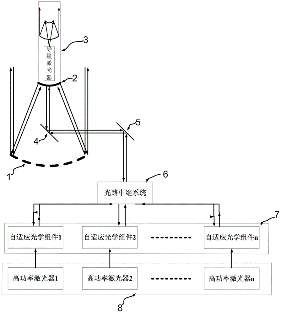
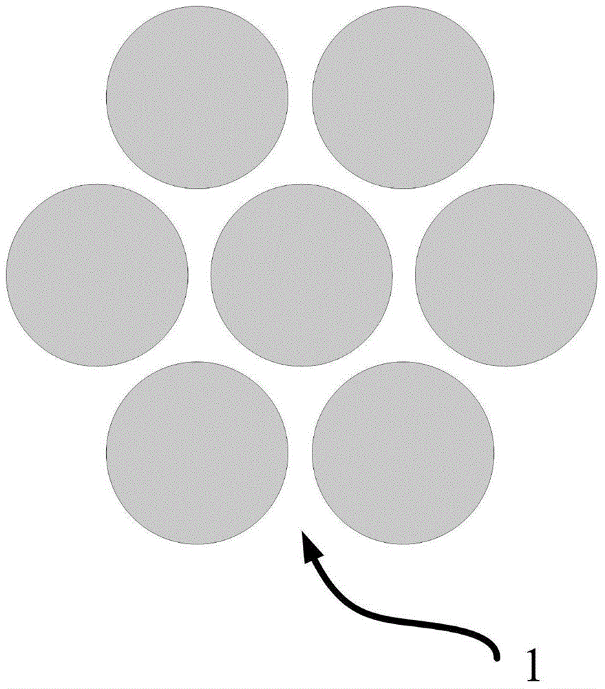
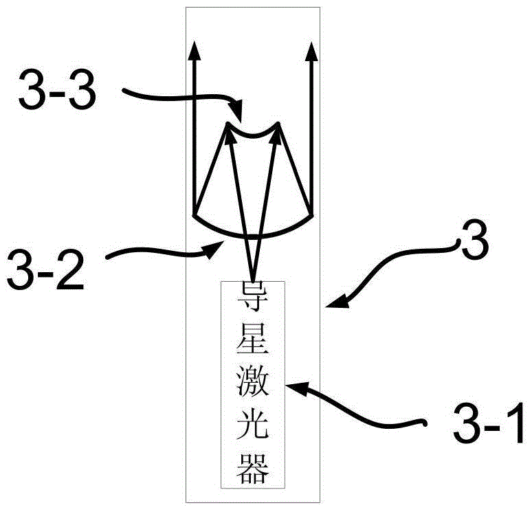
[0017] Specific implementation mode 1. Combination Figure 1 to Figure 6 Description of this embodiment, the laser beam combining space debris removal system based on adaptive optics technology mainly consists of a laser emitting telescope, a laser guide unit 3, an optical path relay system 6, n-way adaptive optics components 7 and n multiple-way high-power Composed of 8 laser emitters. Wherein the laser emitting telescope composed of spliced ​​primary mirror 1 and secondary mirror 2 is installed on a set of support and target tracking system as the main optical system. This support and tracking system is an inherent part of most telescopes. The laser guide star unit 3 is installed on the back of the secondary mirror 2, and emits a beam of laser light to an altitude of about 90 kilometers to form a laser guide star. Enter Adaptive Optics Assembly 7. The adaptive optics component 7 measures the current system wave aberration and corrects it. After the laser beams emitted by ...


PUM


Abstract

A laser beam-combined space debris scavenging system based on the self-adaptive optical technology, relates to the field of space technology, aims to solve the problem that elements in the light path are easy to deform when heated in the process that the space debris is scavenged by the conventional ground high energy laser emitting system. According to the invention, multiple high power laser beams are emitted to the space debris from the ground surface to realize ablation effect on space debris through the stacking of the energies of the multiple beams; in order to improve the action effect of the laser beams on the space debris, the self-adaptive optical technology is adopted in the system for correction of thermal deformation of the optical elements and disturbance caused by atmosphere; and meanwhile, the laser guide star technology is used by the system, so as to improve the capacity of the action on dark weak space targets; the space debris scavenging system is a way, by which space debris scavenging on earth surface is realized, that space debris with different orbit altitudes are scavenged is realized with the utilization of the principle of energy stacking and the adoption of multiple laser beams for emission, the technical realization difficulty of every key unit is decreased, the maintenance is convenient, and the cost is correspondingly reduced.

Description

technical field [0001] The invention relates to the field of space technology, in particular to the technology of removing space debris. Background technique [0002] Space debris refers to man-made objects orbiting around the center of the earth, which generally have no use value. It is the product of human space activities, including stopped spacecraft (such as satellites, space stations, space shuttles, etc.), rocket residues used to launch satellites, debris produced by the separation of multi-stage rockets, and collisions between space objects. fragments etc. With the progress of human space activities, the number of space debris presents a growing trend, and its potential collision risk seriously threatens the safe operation of spacecraft in orbit. [0003] Research on space debris focuses on monitoring and removal. To monitor space debris is to give its position and changes in the sky at every moment, and determine its orbit. Although for some regular space debris...

Claims


Application Information

Patent Timeline
IPC IPC(8): G02B23/00G02B17/06G02B27/06
Inventor 王建立林旭东刘欣悦卫沛锋王亮
Owner CHANGCHUN INST OF OPTICS FINE MECHANICS & PHYSICS CHINESE ACAD OF SCI
Why Eureka
Try Eureka