
Shunt and water replenishing boiler plate

A boiler plate and water replenishment technology, which is applied in the field of cast iron boiler boiler plates to achieve the effects of improving heat exchange efficiency, eliminating dead zone of water flow and prolonging process flow.

Inactive Publication Date: 2014-11-26
天津山姆燃气设备有限公司
View PDF5 Cites 0 Cited by
  • Summary
  • Abstract
  • Description
  • Claims
  • Application Information

AI Technical Summary

Problems solved by technology

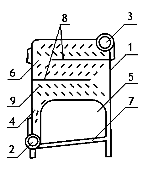
[0005] The beneficial effects of the present invention are: the present invention adds water channel partitions and spoilers on the basis of the original, the water flow can be dispersed when it flows, the heat exchange dead zone is eliminated, the heat exchange surface is increased, and the water flow is prolonged. The process and heat exchange time improve the heat exchange efficiency of the pot piece. The invention also adds a diversion water pipe with a slope of 0~15°, which increases the heat exchange area and overcomes the horizontal water pipe at the lower part of the incomplete water-in-fire structure. Due to the defect that the gas generated by heating is not easy to discharge, it enhances the cooling effect on the lower part of the pot, improves the water circulation, and eliminates the dead zone of water flow. The gap between them also becomes the entrance of the air required for combustion, which makes the flame burn completely and improves the heat exchange capacity of the pot pieces.

Method used


Image

  • Shunt and water replenishing boiler plate

Examples


Embodiment 1

[0010] The invention includes a pot body 1, a water inlet pipe 2, a water outlet pipe 3, a side waterway 4, a hollow cavity 5, a water exchange chamber 6, a water diversion pipe 7, a water channel partition 8, a spoiler 9, and the upper part of the pot body 1 The water exchange chamber 6 is provided with a water outlet pipe 3 on one side, and the water exchange chamber 6 extends downward along the pot body 1, forming side waterways 4 on both sides of the pot body, and exiting at the lower end of the pot body 1. The opposite side of the water pipe 3 is provided with a water inlet pipe 2, and between the extended part of the pot piece water chamber 6 on the opposite side of the water inlet pipe 2 and the water inlet pipe 2, a diversion water pipe 7 with an inclination of 0~15° is arranged, and its diameter is smaller than that of the pot piece The thickness of the main body 1 is provided with a water channel partition 8 on the side wall of the pot body 1, which is layered and sta...

Embodiment 2

[0012] The lower part of the water exchange chamber 6, the side waterway 4, and the branch water pipe 7 form a hollow cavity 5. The flame burns in the hollow cavity 5 to form a radiant furnace. The medium water enters the pot body 1 from the water inlet pipe 2 and flows through the The side waterway 4 and the branch water pipe 7 enter the exchange water chamber 6, and the water flow is forced to disperse by the effect of the spoiler 9, and flows along the water channel formed by the water channel partition plate 8, and the water flow fills the entire pot body 1 as much as possible, and then Flow out from the water outlet pipe 3 to complete the whole heat exchange process.

[0013]


PUM


Abstract

The invention relates to a shunt and water replenishing boiler plate which comprises a boiler plate body, a water inlet pipe, a water outlet pipe, side waterways, a hollow cavity, a heat exchange water chamber, a shunt water pipe, water channel partitions, and spoilers, wherein the heat exchange water chamber is arranged at the upper part of the boiler plate body; the water outlet pipe is arranged on one side of the boiler plate body; the heat exchange water chamber extends downwards along the boiler plate body; the side waterways are formed on the two sides of the boiler plate body; the water inlet pipe is arranged on the opposite side of the water outlet pipe and at the lower end of the boiler plate body; the oblique shunt water pipe is arranged between the water inlet pipe and the opposite side of the water inlet pipe; the water channel partitions are arranged on a side wall of the boiler plate body; and the spoilers are arranged in the heat exchange water chamber. According to the invention, the water channel partitions and the spoilers are added on the original basis to disperse a water flow, eliminate heat exchange dead angles, and prolong a flow path and heat exchange time of water; the oblique shunt water pipe overcomes the defect that gas generated by heating is not easy to exhaust; a cooling effect on the lower part of the boiler plate is improved; and heat exchange capability of the boiler plate is improved.

Description

[0001] technical field [0002] The invention relates to a cast iron boiler pan piece, in particular to a split flow and water replenishment pan piece. Background technique [0003] Cast iron boilers are popular because of their corrosion resistance and long service life. The lower part of the traditional cast iron boiler adopts an annular water jacket structure, and the flame burns in the hollow cavity surrounded by the annular water jacket, forming a kind of water-in-fire The structure, the way the water inside the pot sheet absorbs the heat of the flame is radiation heat exchange, but the amount of air required for the flame combustion of this water-in-fire system is often insufficient, resulting in incomplete combustion of the flame, and the lower part of the hollow cavity is horizontal Tube, the gas generated by heating in the tube is not easy to discharge, which reduces the radiation heat transfer efficiency. The inside of this pot is equipped with round columns and so...

Claims


Application Information

Patent Timeline
Patent Type & Authority Applications(China)
IPC IPC(8): F24H9/00
Inventor 赵楠姚铁强张跟东关怀张师愚马一太赖先楷
Owner 天津山姆燃气设备有限公司
Learn More