Non-contact high-precision calibration method of tool coordinate system of single robot

A technology of tool coordinate system and calibration method, which is applied in the calibration field of industrial robots, and can solve problems such as inability to complete calibration of the robot tool body, affecting accurate control of robot pose, robot parametric programming, and uncontrollability

Active Publication Date: 2014-11-26
SHANGHAI MITSUBISHI ELEVATOR CO LTD
View PDF6 Cites 13 Cited by
  • Summary
  • Abstract
  • Description
  • Claims
  • Application Information

AI Technical Summary

Problems solved by technology

like figure 1 Shown is the robot’s TCP (Tool Coordinate Point, tool coordinate system) calibration method. The operation of this calibration method is relatively cumbersome, and it also has certain requirements for the space point. When the robot needs to keep the position of the space point unchanged, different The attitude is completed by several points; moreover, the calibration accuracy varies from operator to operator, and there are certain uncontrollable factors, which makes the value obtained after calibration have a large error, usually at the millimeter level, and takes a lot of time
The disadvantages of this calibration method cannot meet the requirements of modern production for higher precision of robots, higher efficiency of calibration operations, and higher calibration accuracy
[0005] Chinese patent 201010545419.7 discloses a robot tool coordinate system automatic calibration device and method based on laser tracking measurement, but it only calibrates the robot tool coordinate system, not the entire robot system, which causes even if the accuracy of the tool coordinate system reaches To a certain extent, but because the accuracy of other coordinate sy

Method used


Image

  • Non-contact high-precision calibration method of tool coordinate system of single robot
  • Non-contact high-precision calibration method of tool coordinate system of single robot
  • Non-contact high-precision calibration method of tool coordinate system of single robot

Examples


Embodiment Construction

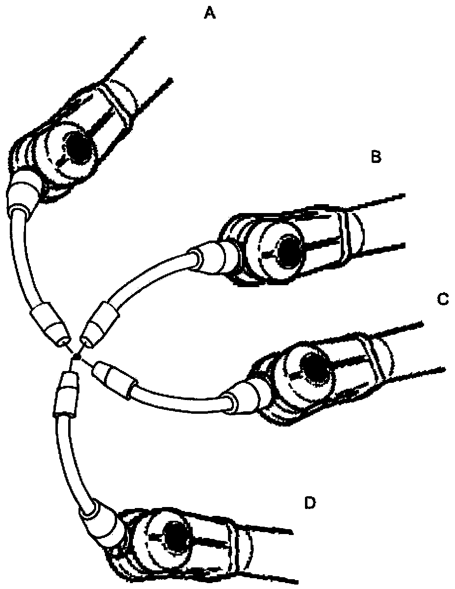
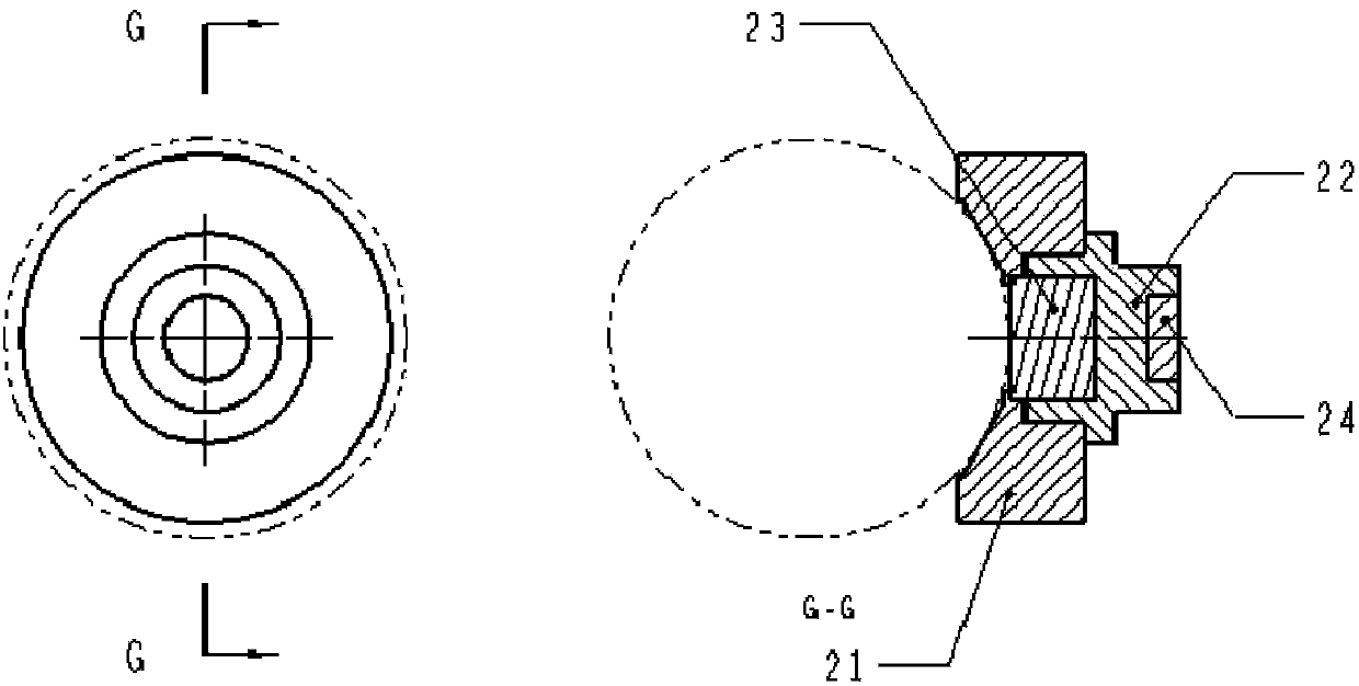
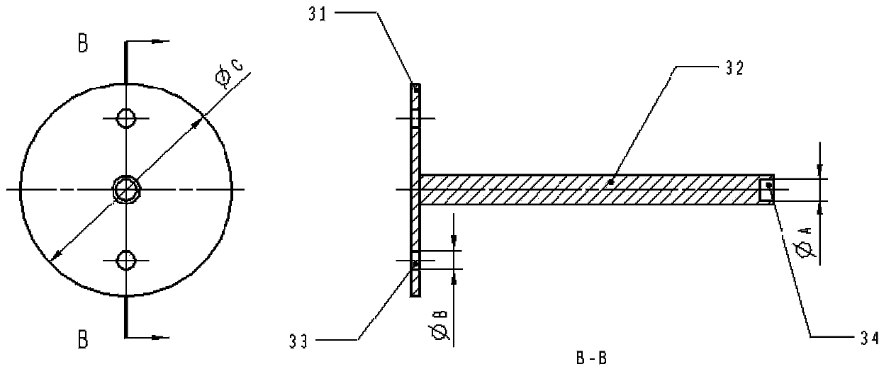
[0148] The present invention adopts the calibration finger tooling installed with the measuring ball, and installs the calibration finger tooling on the robot flange or the tool body; uses the laser measuring instrument to measure the center of the measuring ball (that is, the center point of the measuring ball as the calibration point); The laser measuring instrument has a coordinate system of the laser measuring instrument. The data measured by the laser measuring instrument are processed through the algorithm of coordinate transformation, and the relationship between the coordinate system of the laser measuring instrument and the base coordinate system of the robot and the workpiece coordinate system are respectively established to construct The relationship between the robot's base coordinate system and the workpiece coordinate system and the relationship between the tool coordinate system and the robot end coordinate system, so as to perform non-contact high-precision calib...


PUM


Abstract

The invention discloses a non-contact high-precision calibration method of a tool coordinate system of a single robot, comprising the following steps: first, calibrating a fundamental coordinate system of a robot; second, calibrating a workpiece coordinate system of the robot. The calibration employed by the invention is that a tool sleeve can perform a significantly complete calibration on the tool coordinate system of the robot. The calibration is that the tool sleeve can ensure repeatability of each operation, so as to furthest reduce errors generated by man-made calibration. The method provided by the invention, the non-contact high-precision calibration method of the fundamental coordinate system of the robot, and the non-contact high-precision calibration method of a tool coordinate system of the single robot are cooperated for application, so that basic technical basis is provided to realize accurate transformation of the robot pose, parameterization programming of the robot, high-precision coordination work of a robot group and pose transformation of the robot, resettlement of the robot system, multi-station program share of the robot and locus program of the robot and the like.

Description

technical field [0001] The invention relates to a calibration method for an industrial robot, in particular to a non-contact high-precision calibration method for a tool coordinate system of a single robot. Background technique [0002] The flexible processing and production unit based on industrial robots has become the main development direction of the manufacturing industry. Among them, the accurate control of the robot pose, the parametric programming of the robot, the high-precision coordination work of the robot group, the transformation of the robot pose, and the control of the robot system The needs of relocation, robot multi-station program sharing, robot trajectory planning, etc. are gradually becoming the focus of attention. All of the above aspects require the establishment of accurate models of the actual robot and its working environment, as well as other equipment and tools, so the calibration of the robot’s environmental parameters (workpiece coordinate syste...

Claims


Application Information

Patent Timeline
IPC IPC(8): G01B11/00
Inventor 朱笑奔汪航吴旭
Owner SHANGHAI MITSUBISHI ELEVATOR CO LTD
Why Eureka
Try Eureka