Supercharge Your Innovation With Domain-Expert AI Agents!

Welding method for temperature pipe and reheat cooling section pipe

A technology of reheating and cold section and welding method, which is applied in the field of steel welding, can solve problems such as joint failure, creep resistance, durable strength and plasticity decline, and achieve good reliability, satisfactory weld performance and good crack resistance Effect

Inactive Publication Date: 2014-12-03
华能兰州西固热电有限公司
View PDF7 Cites 6 Cited by
  • Summary
  • Abstract
  • Description
  • Claims
  • Application Information

AI Technical Summary

Problems solved by technology

[0010] (2) When carbon steel and austenitic steel are welded, the formation of a transition layer will lead to the formation of a de-C layer on the pearlite base metal near the gold fusion line and softening, and the formation of a high-strength layer on the side of the austenitic steel weld The hardness of the black C-penetrating layer causes the decline of creep resistance, durable strength and plasticity in this area, resulting in early failure of the joint

Method used


Image

  • Welding method for temperature pipe and reheat cooling section pipe
  • Welding method for temperature pipe and reheat cooling section pipe
  • Welding method for temperature pipe and reheat cooling section pipe

Examples


Embodiment 1

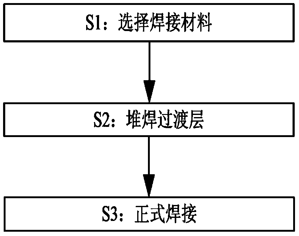
[0029] Such as figure 1 As shown, preferably, this embodiment provides a method for welding a temperature tube and a reheated cold section tube, and the steps include:

[0030] S1, select welding material:

[0031] Choose high chromium nickel austenitic stainless steel welding wire or nickel-based welding wire as welding material. Now choose Inconel 82 welding wire, the chemical composition of the welding wire is shown in Table 1.

[0032] Table 1 Chemical composition of welding wire:

[0033] Welding wire NiC Mn Nb SiCuCr Ti S, P Inconel 82 670.103.02.50.50.25200.750.02

[0034] The welding material is Inconel 82 welding wire. The Inconel 82 welding wire includes 67% Ni, 0.1% C, 3.0% Mn, 2.5% Nb, 0.5% Si, 0.25% Cu, 20% Cr, 0.75% Ti, 0.02% S and P.

[0035] Before welding, clean the temperature tube and the reheating cold section tube: before the weldment is assembled, the oil, paint, rust, scale, etc. on the surface of the groove and the inner and outer walls of the adjacent bas...

Embodiment 2

[0049] S1, select welding material:

[0050] Choose high chromium nickel austenitic stainless steel welding wire or nickel-based welding wire as welding material. Now choose Inconel 82 welding wire

[0051] S2, over-surfacing layer:

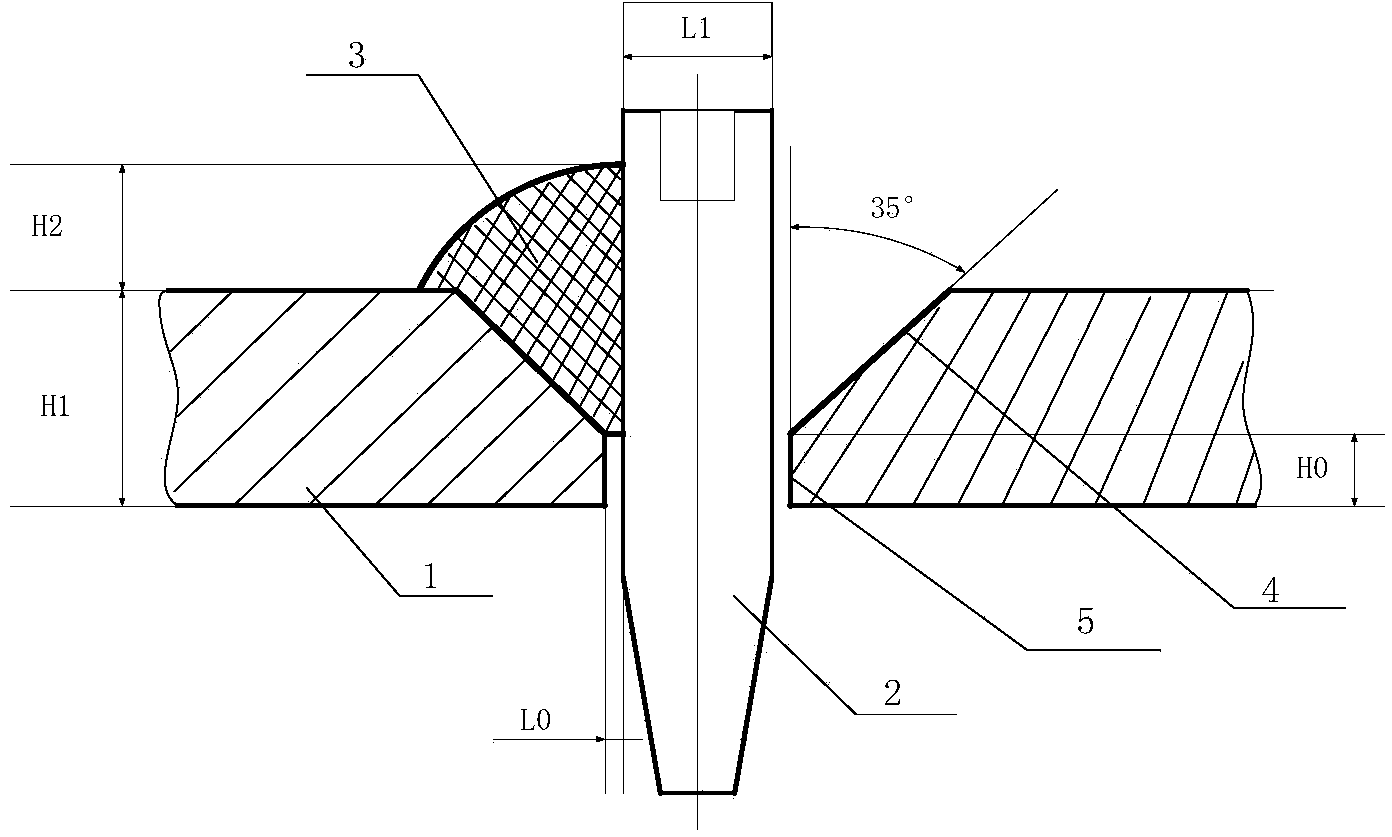
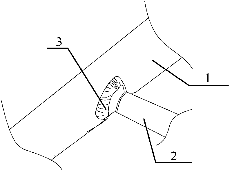
[0052] The transition layer is welded on the base material side of the reheated cold section pipe with the welding material in step 1, and the transition layer includes five layers.

[0053] S3, formal welding:

[0054] Find the welding center of the reheated cold section tube and the temperature tube, and weld the temperature tube and the reheated cold section tube by electric welding with the welding material in step 1.

[0055] The welding method in step S3 is manual argon tungsten arc welding; and the welding voltage range is 25V, the welding current is direct current, the current is 90A, and the welding speed is 80mm / min; in the welding method of step three, the first layer welding speed 60mm / min, the second layer welding speed is 65mm / min, the third...


PUM

PropertyMeasurementUnit
thicknessaaaaaaaaaa
thicknessaaaaaaaaaa
thicknessaaaaaaaaaa

Abstract

The invention provides a welding method for a temperature pipe and a reheat cooling section pipe. The welding method is characterized by comprising the steps that firstly, high chromium nickel austenitic stainless steel welding wires or nickel-based welding wires are adopted as welding materials; secondly, at least two transition layers are formed in a bead weld mode on the parent metal side of the main reheat cooling section pipe through using welding materials selected in the first step; welding centers of the reheat cooling section pipe and the temperature pipe are found, and the temperature pipe and the reheat cooling section pipe are welded together through electric welding of the welding materials selected in the first step. The selected welding materials meet the requirements of parent metal of the main reheat cooling section pipe, the coefficient of linear expansion of welding seam materials is within the range of the coefficient of linear expansion of materials of the temperature pipe and the reheat cooling section pipe, and therefore the requirement for the heat crack resisting performance of welding seam metal and the high temperature performance of a welding connector can be met.

Description

Technical field [0001] The invention relates to the technical field of steel welding, in particular to a welding method of a temperature tube and a reheated cold section tube. Background technique [0002] In boilers used in power plants, the temperature tube is usually selected as 1Cr18Ni9Ti, and the reheating and cold section tube is selected as A672B70CL32P22. A672B70CL32+1Cr18Ni9T temperature pipe seat welding joint belongs to dissimilar steel welding joint, namely: austenite and ferrite welding. Although we have mature welding processes for the respective welding processes and welding methods of the two metal materials A672B70CL32 and 1Cr18Ni9Ti, the welding process of the A672B70CL32P22+1Cr18Ni9Ti dissimilar steel is especially similar to the type of reheating and cold section pipe seat. Fillet joints, due to the big difference in the chemical composition and metallographic structure of the two materials, and the big difference in physical properties, it is prone to large-...

Claims


Application Information

Patent Timeline
Patent Type & Authority Applications(China)
IPC IPC(8): B23K9/167B23K35/30
CPCB23K9/167B23K9/0052B23K9/235B23K35/304
Inventor 王沛陈世炯戚晓东郝哲然岳潇刘君然陈蕾
Owner 华能兰州西固热电有限公司
Features
  • R&D
  • Intellectual Property
  • Life Sciences
  • Materials
  • Tech Scout
  • Unparalleled Data Quality
  • Higher Quality Content
  • 60% Fewer Hallucinations
Learn More