Nerve blocking device using ultrasonic guide

A nerve block and ultrasound technology, applied in the field of ultrasound-guided nerve block devices and trocars, can solve problems such as nerve damage, and achieve the effects of not easily damaging nerves, reducing nerve damage, and not easily slipping out.

Active Publication Date: 2014-12-10
HENAN TUOREN MEDICAL DEVICE GRP
View PDF6 Cites 6 Cited by
  • Summary
  • Abstract
  • Description
  • Claims
  • Application Information

AI Technical Summary

Problems solved by technology

[0004] The purpose of the present invention is to provide a nerve block device that is beneficial to ultrasound guidance, and the nerve block device that is beneficial to ultrasound guidance will solve the technical problem that the nerve block device in the prior art is likely to cause nerve damage

Method used


Image

  • Nerve blocking device using ultrasonic guide
  • Nerve blocking device using ultrasonic guide
  • Nerve blocking device using ultrasonic guide

Examples


Embodiment 1

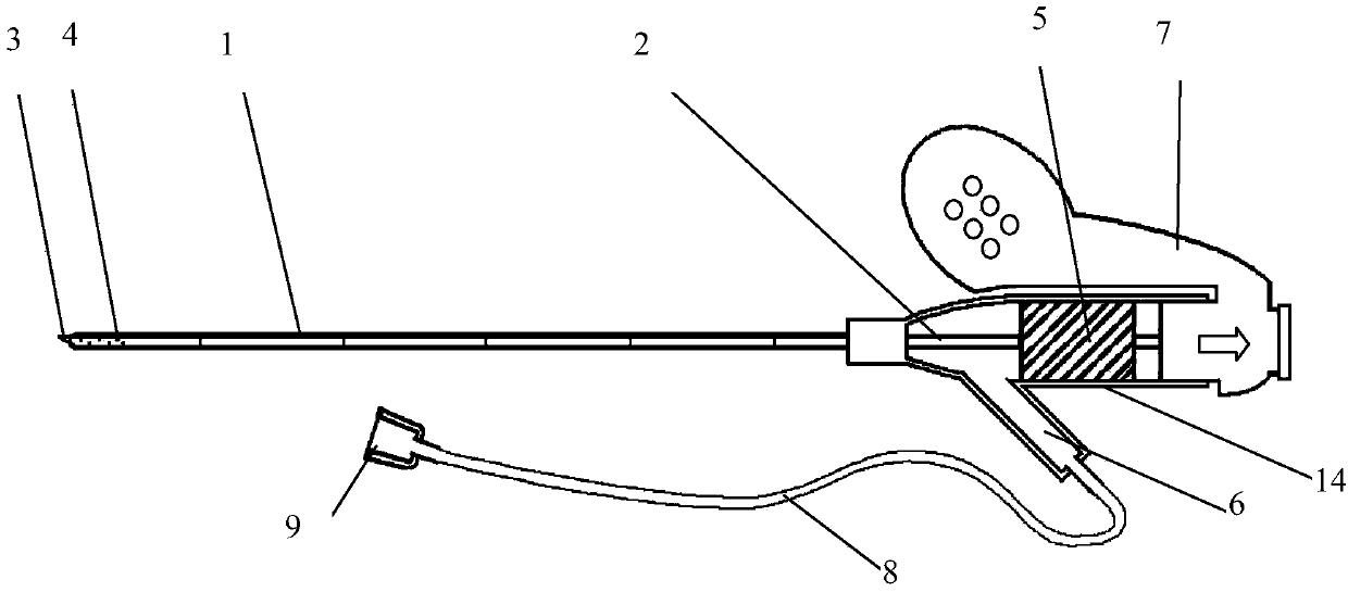
[0027] like figure 1 , figure 2 , image 3 As shown, as shown, a peripheral nerve block device of the present invention is composed of a needle core 2 and a hollow sleeve 1, and the needle core 2 is set in the sleeve 1, wherein the The front end of the needle core 2 is provided with a needle point 3, the needle point 3 extends out of the front end surface of the sleeve 1, and the horizontal axis of the needle point 3 has a micro-dentate structure, the front end of the sleeve 1 At least one side hole 4 is provided on the side wall of the casing, and a connecting pipe 14 is fixedly arranged at the tail end of the sleeve pipe 1. The inner diameter of the connecting pipe 14 is larger than the inner diameter of the sleeve pipe. The extension line of the central axis coincides, a rubber plunger 5 is arranged in the connecting pipe 14, the needle core 2 passes through the rubber plunger 5, and the tail end of the needle core 2 is fixedly provided with a hand-holding wing 7. Hand ...

Embodiment 2

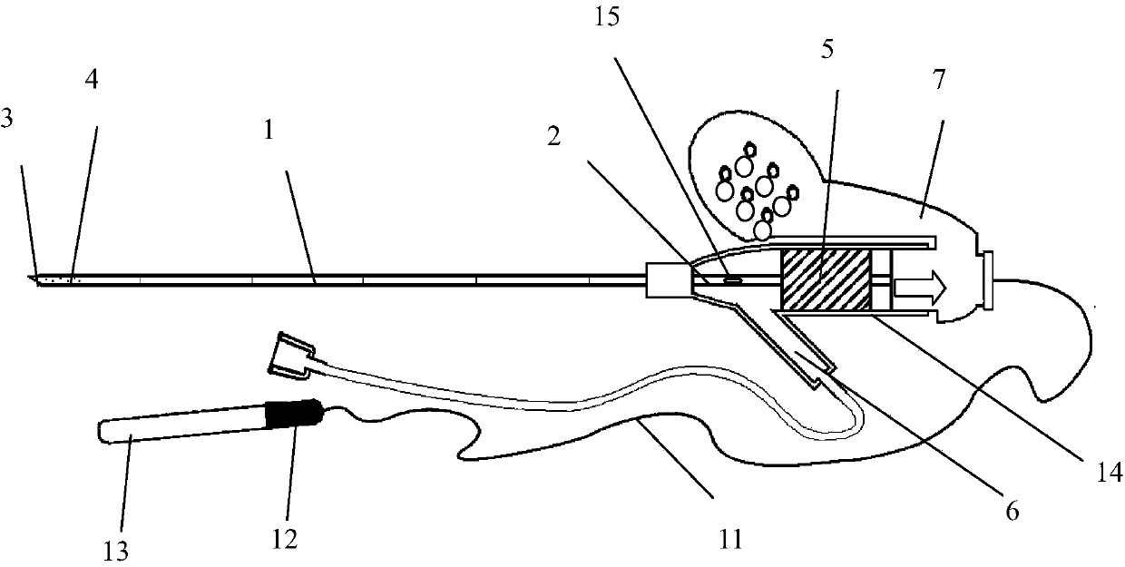
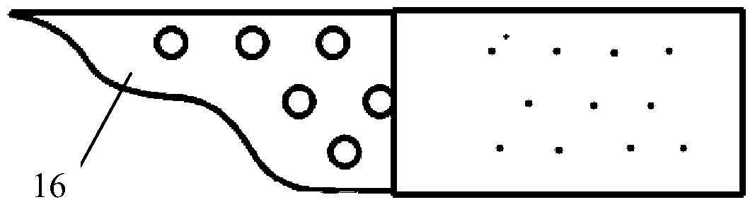
[0035] like figure 2 , image 3 and Figure 4As shown, a peripheral nerve block device of the present invention is composed of a hollow sleeve 1, a needle core 2 is disposed in the sleeve 1, and a needle point 3 is disposed at the top of the needle core 2, The needle tip 3 protrudes from the top of the sleeve 1, at least one side hole 4 is provided on the side wall of the front end of the sleeve 1, and a post is provided at the tail end of the sleeve 1 The plug 5, the tail end of the sleeve 1 is also provided with a side tube 6, the side tube 6 is arranged at the front end of the plunger 5, the side tube 6 and the sleeve 1 The tail end of the sleeve 1 is provided with a hand-holding wing 7, the needle core 2 passes through the plunger 5, and the needle core 2 is connected to the hand-holding wing 7 One end of the needle core 2 protrudes from the hand-holding wing 7, the slope of the needle point 3 is provided with a microdentate structure 16, and the outer surface of the n...


PUM


Abstract

A nerve blocking device using ultrasonic guide comprises a hollow bush. A hollow needle core is disposed in the bush. A needle tip is disposed at the top end of the needle core. The needle tip extends out of the top end of the bush. A micro-tooth-shaped structure is disposed on the slope of the needle tip. The outer surface, close to the needle tip, of the needle core is provided with a concave-convex structure. A plurality of lateral holes are formed in the lateral wall of the front end of the bush. A plurality of materials which are parallel with the long axis of the bush, can intensify ultrasonic development effect and are X-ray-tight are embedded into the bush. A rubber plunger is disposed in the tail end of the bush. A lateral tube is further arranged at the tail end of the bush. The lateral tube is disposed at the front end of the rubber plunger. The lateral tube is communicated with the bush. The nerve blocking device has the advantages that continuous peripheral nerve blocking can be completed under ultrasonic guide, reflecting development effects can be enhanced by the zigzag structure of the annular surface of the needle core tip and the concave-convex structure on the outer surface of the needle core, development under ultrasonic guide can be achieved, and the nerve blocking device is simple to operate, high in accuracy and less prone to nerve damage.

Description

[0001] Technical field: [0002] The present invention relates to articles for human life, in particular to medical instruments, in particular to trocars, and in particular to a nerve block device which is beneficial to ultrasound guidance. Background technique: [0003] The continuous peripheral nerve block technique can achieve the effects of prolonged anesthesia, postoperative analgesia and sympathetic nerve block according to the needs of the operation, and at the same time can realize divided administration, thereby reducing the risk of local anesthetic poisoning. It has been widely used in clinical anesthesia and pain treatment, and it is also one of the main methods of multimodal analgesia. In order to reduce the complications of anesthesia, modern anesthesia has entered the era of visualization, and ultrasound has been widely used in various methods of anesthesia. Traditional nerve block can be completed by anatomical positioning blind detection method or nerve stim...

Claims


Application Information

Patent Timeline
Patent Type & Authority Applications(China)
IPC IPC(8): A61M5/145A61M5/178A61B5/05A61B8/08
Inventor 余斌靳令经邹天笑谢书奇张毓文何苗张晓庆
Owner HENAN TUOREN MEDICAL DEVICE GRP
Why Eureka
Try Eureka