
Cleaning method and device special for 3PE erosion resistant layer of oil and gas pipeline

A technology for oil and gas pipelines and cleaning equipment, used in cleaning methods and utensils, chemical instruments and methods, cleaning hollow objects, etc., can solve problems affecting pipeline performance, complicated operations, mechanical damage to pipeline surfaces, etc. Wide range of diameters, easy to carry during construction

Active Publication Date: 2014-12-10
TIANJIN NAISI ENG TECH
View PDF6 Cites 0 Cited by
  • Summary
  • Abstract
  • Description
  • Claims
  • Application Information

AI Technical Summary

Problems solved by technology

[0003] However, in the process of maintenance and emergency repair, the removal of the anti-corrosion layer has become a difficult problem hindering the emergency repair. At present, there are three main methods. The first is to use a fire and then remove it with a shovel. It is often removed several times, and the efficiency is high. It is low and has an open flame, which is unsafe and pollutes the environment; the second is to use mechanical or manual scraping, which often causes mechanical damage to the surface of the pipeline and may generate sparks; the third is to use electromagnetic heating or infrared heating technology Heat the pipeline to soften the anti-corrosion layer and then manually clean it one by one to remove the anti-corrosion layer. This technology consumes a lot of power, has low efficiency, and is complicated to operate. Due to the high temperature (about 300 degrees), it will be damaged to a certain extent. The metal crystal structure of the pipe body affects the performance of the pipe

Method used


Image

  • Cleaning method and device special for 3PE erosion resistant layer of oil and gas pipeline
  • Cleaning method and device special for 3PE erosion resistant layer of oil and gas pipeline

Examples


Embodiment Construction

[0019] The present invention will be described in detail below in combination with specific embodiments.

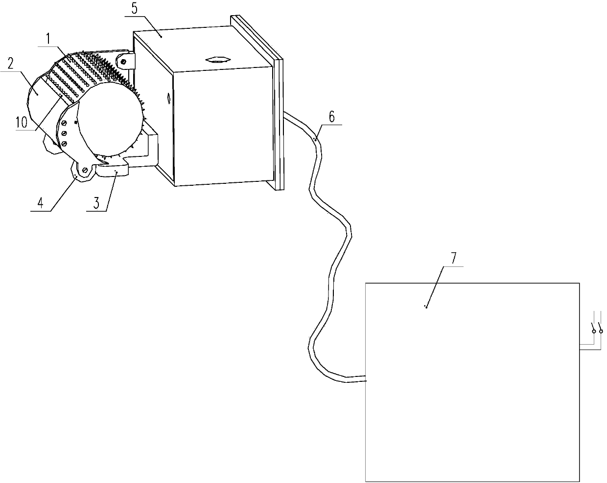
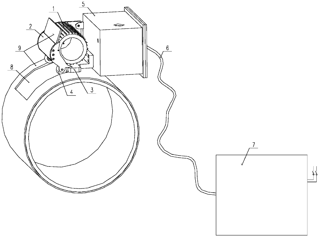
[0020] A cleaning method dedicated to the 3PE anti-corrosion layer of oil and gas pipelines,

[0021] Including the following steps:

[0022] The first step is to break the opening of the polyethylene layer, then press it into the roller of the machine, turn the roller clockwise to automatically tighten, and the whole machine is close to the pipe wall.

[0023] The second step is to aim the electromagnetic wave generator at the area to be cleaned, and use waveguide technology to guide the electromagnetic wave to act on a specific area, and directly destroy the molecular structure of the adhesive layer through electromagnetic energy, making it harden and fail instantly at room temperature;

[0024] In the third step, the PE layer is separated from the epoxy layer under the action of mechanical force, and the polyethylene layer is separated from the pipe wall, and the roll...


PUM


Abstract

The invention provides a cleaning method special for a 3PE erosion resistant layer of an oil and gas pipeline. The method includes the steps that firstly, an opening is formed in a polyethylene layer, then the polyethylene layer is pressed into a machine rolling wheel, the rolling wheel is rotated clockwise to automatically strain the rolling wheel, and a complete machine is tightly attached to a tube wall; secondly, an electromagnetic wave generator is aligned with a region to be cleaned, electromagnetic waves are directionally guided to act on a specific region through a waveguide technology, and the molecular structure of an adhesive layer is directly damaged through electromagnetic energy so that the molecular structure can be hardened and invalid instantly at normal temperature; thirdly, the PE layer is separated from an epoxy layer under the action of mechanical force, the polyethylene layer is separated from the tube wall immediately, and the rolling wheel outwards conveys the polyethylene layer continuously. By means of the cleaning method and device special for the 3PE erosion resistant layer of the oil and gas pipeline, low consumption of electric energy is achieved without damaging the pipeline, so that automatic operation is achieved, the applicable tube diameter range is wide, and work efficiency is improved. The temperature is not higher than 70 degrees, the cleaning method and device are easy and convenient to operate, convenient to construct and carry, high in efficiency and capable of continuous operation. The cleaning method and device are wide in applicable range and free of tube diameter limitation.

Description

technical field [0001] The invention relates to the technical field of pipeline maintenance and emergency repair, in particular to a method and equipment for cleaning 3PE anticorrosion layers of oil and gas pipelines. Background technique [0002] The existing 3PE anti-corrosion coating of oil and gas pipelines is mainly made of polyethylene and high-density polyethylene. 3PE anti-corrosion generally consists of three layers: the first layer of epoxy powder coating, the second layer of adhesive layer, and the third layer of polyethylene Layer, the three materials are mixed and integrated, and processed to make it firmly combined with the steel pipe to form an excellent anti-corrosion layer. [0003] However, in the process of maintenance and emergency repair, the removal of the anti-corrosion layer has become a difficult problem hindering the emergency repair. At present, there are three main methods. The first is to use a fire and then remove it with a shovel. It is often r...

Claims


Application Information

Patent Timeline
IPC IPC(8): B08B9/047
CPCB08B9/047
Inventor 孙海华
Owner TIANJIN NAISI ENG TECH
Learn More