High-efficiency steelmaking converter system
A steelmaking converter and high-efficiency technology, which is applied in the field of industrial smelting furnaces and high-efficiency steelmaking converter systems, can solve the problems of the alloy yield to be improved, the cleanliness of molten steel, and the high cost of steelmaking, so as to improve the cleanliness of molten steel and improve The effect of improving the service life and improving the quality of molten steel
- Summary
- Abstract
- Description
- Claims
- Application Information
AI Technical Summary
Problems solved by technology
Method used
Image

Examples
Embodiment Construction
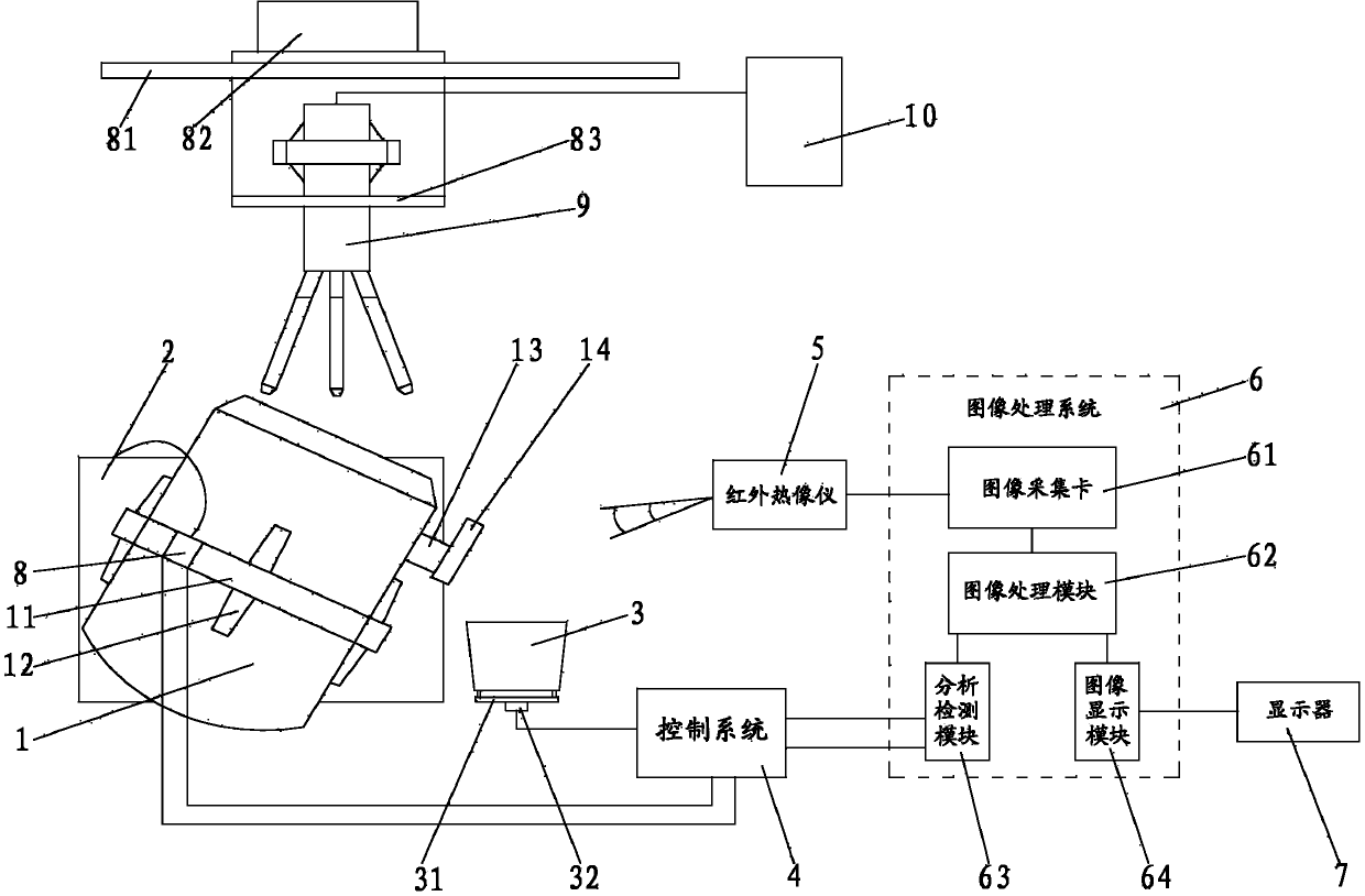
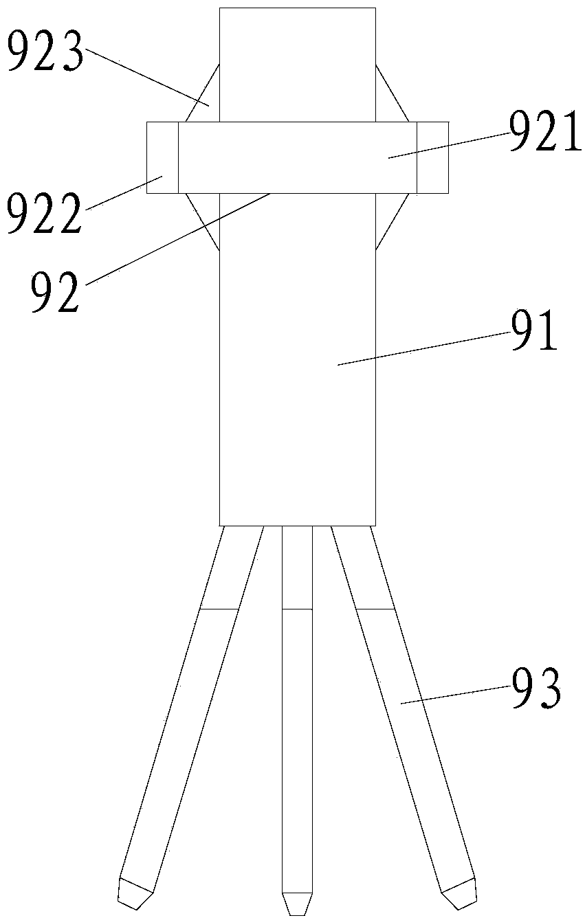
[0022] refer to figure 1 , figure 2 , image 3 , Figure 4 and Figure 5 , a high-efficiency steelmaking converter system in the present invention includes a converter 1, an oxygen lance system, a tilting mechanism 2, a ladle 3, a control system 4, an infrared thermal imager 5, an image processing system 6 and a display 7, and the oxygen lance system is located at Above the converter 1, the oxygen lance system is composed of a suspension rod 81, a hydraulic control system 82 and an oxygen lance assembly 9. The hydraulic control system 82 is installed on the suspension rod 81, and the oxygen supply system 10 is connected with the oxygen lance assembly 9. The lance assembly 9 is installed on the suspension rod 81 through the lifting device 83. The oxygen lance assembly 9 includes an oxygen inlet main pipe 91, a rotating disk 92 and several oxygen lances 93. The rotating disk 92 is installed on the oxygen inlet main pipe 91, and the oxygen inlet main pipe 91 A number of oxyg...
PUM
 Abstract
Description
Claims
Application Information
PatSnap Eureka turns technology decisions into work you can execute. Powered by our Innovation Knowledge Graph, it runs expert workflows across engineering, life sciences, materials and intellectual property. Get your review-ready output in minutes.


