

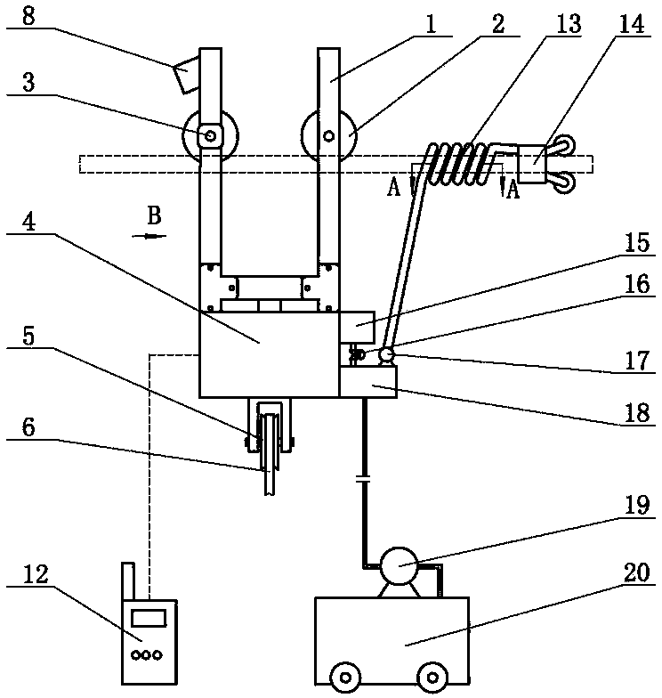
Live working remote control sliding device
A technology for live work and skids, applied in the direction of overhead lines/cable equipment, etc., can solve the problem that the mechanical cleaning device is easily entangled, and achieve the effect of saving cleaning time, low manufacturing cost, and reducing line failures.
- Summary
- Abstract
- Description
- Claims
- Application Information
AI Technical Summary
Problems solved by technology
Method used
Image

Examples
preparation example Construction
[0016] The present invention also provides a preparation method of a charged cleaning agent for electrical equipment, the steps are as follows:
[0017] ①Add 1-2 parts of polyvinylpyrrolidone and 1-3 parts of pentaerythritol to the mixture of 15-25 parts of propylene glycol butyl ether and 4-6 parts of N-methyl-2-pyrrolidone, stir and heat up to 50-70℃ , keep warm for 1-2 hours, cool to 20-30°C to obtain mixed solution A, set aside;
[0018] ②Add 1-3 parts of dodecyl dimethyl quaternary ammonium betaine to the mixture of 10-20 parts of triethanolamine and 3-5 parts of ethylene glycol monobutyl ether, stir and heat up to 70-90°C , after 1-2 hours, cool to 20-30°C to obtain mixed solution B, set aside;
[0019] ③ mix the mixed solution A obtained in step ①, the mixed solution B obtained in step ②, 20-30 parts of trichlorethylene, 15-25 parts of carbon tetrachloride and 5-10 parts of N-fatty acyl glutamic acid ethanolamine salt to obtain Charge cleaning agent for electrical equ...
Embodiment 1
[0026] A charged cleaning agent for electrical equipment, consisting of the following components in parts by weight: 20 parts of trichlorethylene, 25 parts of carbon tetrachloride, 15 parts of propylene glycol butyl ether, 10 parts of triethanolamine, N-fatty acyl glutamic acid 5 parts of ethanolamine salt, 1 part of polyvinylpyrrolidone, 1 part of pentaerythritol, 4 parts of N-methyl-2-pyrrolidone, 3 parts of ethylene glycol monobutyl ether and 1 part of dodecyl dimethyl betaine.
Embodiment 2
[0028] A charged cleaning agent for electrical equipment, consisting of the following components in parts by weight: 30 parts of trichlorethylene, 15 parts of carbon tetrachloride, 25 parts of propylene glycol butyl ether, 20 parts of triethanolamine, N-fatty acyl glutamic acid 10 parts of ethanolamine salt, 2 parts of polyvinylpyrrolidone, 3 parts of pentaerythritol, 6 parts of N-methyl-2-pyrrolidone, 5 parts of ethylene glycol monobutyl ether and 3 parts of dodecyl dimethyl betaine.
PUM
 Abstract
Description
Claims
Application Information