Control circuit of step-down dcdc converter

A control circuit, logic control circuit technology, applied to the direction of conversion equipment without intermediate conversion to AC, can solve the problems of reducing the current change rate, increasing the volume, output voltage overshoot or large drop, etc., to increase the switching frequency , to avoid adverse effects, to avoid the effect of audio noise

Active Publication Date: 2017-02-08
SG MICRO
View PDF5 Cites 0 Cited by
  • Summary
  • Abstract
  • Description
  • Claims
  • Application Information

AI Technical Summary

Problems solved by technology

The inventor thinks that there are corresponding defects or deficiencies in the following attempted solutions: 1) this kind of capacitor is changed into a polyester film capacitor with little electrostrictive effect, which can basically eliminate the noise produced by the capacitor, but this kind of capacitor Poor stability and high loss
2) Increase the output capacitance, but it will increase the volume; 3) Delay the response time of the circuit, and correspondingly reduce the current change rate, thus playing a certain inhibitory effect
But it will cause a large overshoot or drop of the output voltage, affecting performance, accuracy and reliability
4) The step-down DC-DC converter always works in Forced PWM (PWM-Pulse WidthModulation / pulse width modulation) mode, that is, even if the system does not require such a high switching frequency, it still maintains the original frequency without frequency reduction. But the power consumption is large and the efficiency is low

Method used


Image

  • Control circuit of step-down dcdc converter

Examples


Embodiment Construction

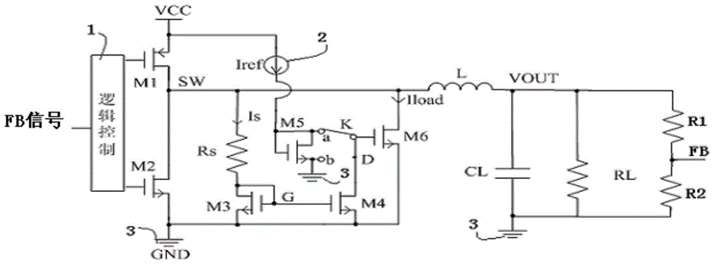
[0017] Below with the accompanying drawings ( figure 1 ) to illustrate the present invention.

[0018] figure 1 It is a structural schematic diagram of the control circuit of the step-down DC-DC converter implementing the present invention. like figure 1 As shown, the control circuit of the step-down DCDC converter includes a first PMOS transistor M1 and a second NMOS transistor M2, the gate of the first PMOS transistor M1 and the gate of the second NMOS transistor M2 are respectively connected with logic control The circuit 1 is connected, the drain of the first PMOS transistor M1 and the drain of the second NMOS transistor M2 are connected to each other to form the first node, that is, the switch node SW, and the source of the second NMOS transistor M2 is connected to the ground terminal 3 The source of the first PMOS transistor M1 is connected to the input voltage terminal VCC; the switch node SW is connected to the output voltage terminal VOUT through an inductor, betwe...


PUM


Abstract

The invention discloses a control circuit for a step-down DCDC converter. The control circuit is beneficial for guaranteeing the performance index of step-down DCDC and beneficial for avoiding audio-frequency noise, and comprises a first PMOS pipe and a second NMOS pipe, wherein the grid electrode of the first PMOS pipe and the grid electrode of the second NMOS pipe are connected with a logic control circuit respectively; the drain electrode of the first PMOS pipe and the drain electrode of the second NMOS pipe are connected with each other so as to form a switching node; the source electrode of the second NMOS pipe is connected with a grounding end; the source electrode of the first PMOS pipe is connected with an voltage input end; the switching node is connected with an voltage output end through electrical inductance; an intermediate node is formed between the switching node and the electrical inductance or between the electrical inductance and the voltage output end; the intermediate node is divided into two routes; the first route of the intermediate node is connected with a sampling resistor, a third NMOS pipe and a grounding end in sequence; the second route of the intermediate node is connected with the grounding end; the grid electrode of a sixth NMOS pipe is connected with the fixed end of a mode switch; the fixed end is connected with the grounding end through a fourth NMOS pipe; the movable end of the mode switch is selectively connected with a light-loading mode end and a regular-loading mode end; a feedback node is arranged at the voltage output end; the feedback node is connected with the logic control circuit.

Description

technical field [0001] The invention relates to the step-down DCDC converter technology, in particular to a control circuit of the step-down DCDC converter, which not only helps to ensure the performance index of the step-down DCDC, but also helps avoid audio noise. Background technique [0002] In the step-down DCDC converter, it mainly provides energy for the output through the periodic switching of the switching tube and the energy storage principle of the inductor and capacitor. DC (Direct Current) refers to direct current, and DCDC (also denoted as DC-DC, direct current -direct current) refers to a DC-to-DC conversion that changes the DC parameters. Among them, the periodic switching of the switching tube is one of the main losses of the system. When the load is light and the output voltage reaches the threshold, the system no longer needs to provide energy for the output through such frequent switching of the switch tube. In order to reduce power consumption, the syst...

Claims


Application Information

Patent Timeline
Patent Type & Authority Patents(China)
IPC IPC(8): H02M3/07
Inventor 陈建春
Owner SG MICRO
Why Eureka
Try Eureka