Water distribution structure and water distribution method of SPE (Solid Phase Extraction) electrolytic tank
An electrolytic cell and wastewater technology, which is applied in the field of water distribution structure of SPE electrolytic cell, can solve the problems of increasing operating costs and increasing energy consumption.
- Summary
- Abstract
- Description
- Claims
- Application Information
AI Technical Summary
Problems solved by technology
Method used
Image
Examples
Embodiment 1
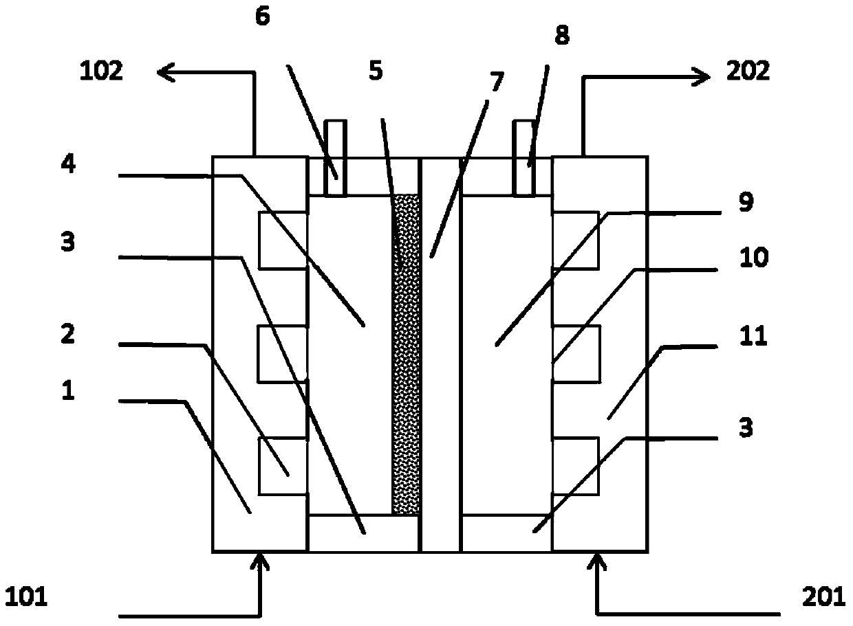
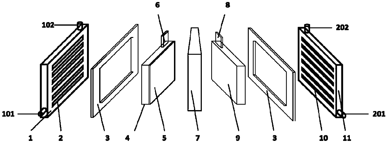
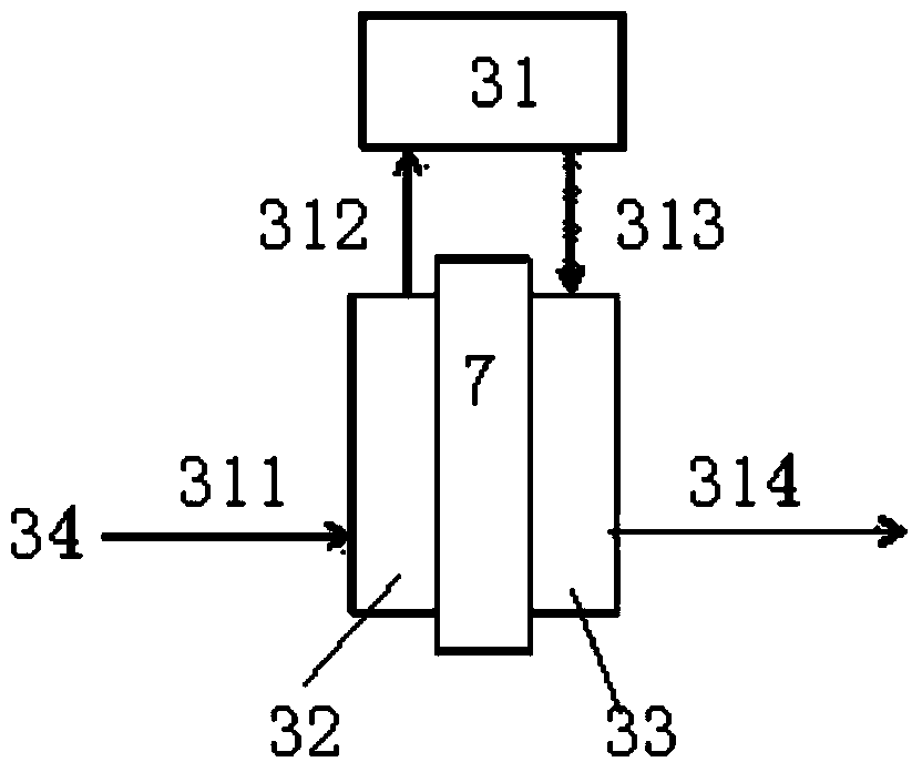
[0071] The SPE electrolyzer adopts Ti wire woven mesh, and is coated with SnCl 4 and SbCl 3 (According to 9:1, total concentration 1.1mol / L) butanol solution, drying at 125°C for 5 minutes, thermal decomposition and sintering at 500°C for 5 minutes, and reciprocating operation 10 times to prepare Ti / SnO 2 -Sb 2 o 5 Solid solution anode catalyst layer 5; nickel mesh is used as the cathode, and the cathode and anode are separated by an ion exchange membrane 7 (such as Nafion), and the effective area of the electrodes is 150cm 2 . The operation mode of SPE electrolytic cell for electrooxidation treatment of coking wastewater is as follows: SPE electrolytic cell distributes water according to water distribution method a (such as image 3 ), that is, the coking wastewater enters the anode of the SPE electrolyzer at a certain flow rate (step 311), and after the electrolytic oxidation of the anode of the electrolyzer, the treated water flows into the sump (step 312); the water ...
Embodiment 2
[0076] The SPE electrolyzer adopts Ti wire braided net, and the preparation method of the anode catalytic layer is as embodiment 1; Adopt the nickel net as the cathode, the cathode and the anode are separated by the ion exchange membrane 7 (such as Nafion), and the electrode effective area is all 150cm 2 . The operation mode of SPE electrolytic cell for electrooxidation treatment of coking wastewater is as follows: SPE electrolytic cell distributes water according to water distribution method b (such as Figure 4 ), that is, the coking wastewater enters the SPE electrolyzer anode (step 321) with the flow rate Q1, and after the electrolytic oxidation of the electrolyzer anode, the treated water enters the sump (step 322); a part of the water in the sump enters with the flow rate Q2 of 10-50% Q1 The cathode of the electrolyzer (step 323), after the cathode is electrolyzed to produce hydrogen, flows back into the water collection tank (step 324); the final treated water flows out...
Embodiment 3
[0081] The SPE electrolyzer adopts Ti wire braided net, and the preparation method of the anode catalytic layer is as embodiment 1; Adopt the nickel net as the cathode, the cathode and the anode are separated by the ion exchange membrane 7 (such as Nafion), and the electrode effective area is all 150cm 2 . The SPE electrolytic cell distributes water according to the water distribution method e (such as Figure 5 ), the specific operation mode is as follows: coking wastewater enters the cathode of the SPE electrolyzer at a flow rate Q (step 351), and after hydrogen is electrolyzed at the cathode of the electrolyzer, the wastewater enters the sump (step 352); the water in the sump enters the electrolyzer at a flow rate Q The anode (step 353), after anodic electro-oxidation treatment, finally flows out of the SPE anode (step 354). The SPE electrolyzer is fed with direct current between the cathode and the anode, and operates in a constant current charging mode.
[0082] When th...
PUM
| Property | Measurement | Unit |
|---|---|---|
| Effective area | aaaaa | aaaaa |
Abstract
Description
Claims
Application Information
 - R&D
- Intellectual Property
- Life Sciences
- Materials
- Tech Scout
- Unparalleled Data Quality
- Higher Quality Content
- 60% Fewer Hallucinations
Browse by: Latest US Patents, China's latest patents, Technical Efficacy Thesaurus, Application Domain, Technology Topic, Popular Technical Reports.
© 2025 PatSnap. All rights reserved.Legal|Privacy policy|Modern Slavery Act Transparency Statement|Sitemap|About US| Contact US: help@patsnap.com


