
FPGA (field programmable gate array)-based method for implementing ship-navigation radar transmitting and receiving system

A ship navigation and system implementation technology, applied in the field of radar system, ship navigation radar transmitting and receiving subsystem, can solve the problems affecting the sensitivity of the whole machine, inconvenient system integration, large space of the circuit board, etc., to improve the working performance and design The effect of compactness and simplified design

Inactive Publication Date: 2014-12-17
南京信大电子科技有限公司
View PDF4 Cites 6 Cited by
  • Summary
  • Abstract
  • Description
  • Claims
  • Application Information

AI Technical Summary

Problems solved by technology

[0008] For the non-coherent ship navigation radar, although the automatic gain control circuit after the RF receiving front end can achieve a large dynamic range, the circuit is often composed of multiple modules, which is susceptible to electromagnetic interference, and the circuit is complex and has poor stability.
In addition, it can be found from the operating instructions and technical maintenance manuals of related radars that the analog-to-digital conversion circuit and the large dynamic range intermediate frequency amplifier circuit are usually boarded separately in the current intermediate frequency signal processing circuit, and the circuits are connected by cables. On the one hand, the form will lead to a larger space occupied by the circuit board, which is not convenient for system integration and miniaturization; on the other hand, it will also affect the sensitivity of the whole machine due to external interference

Method used


Image

  • FPGA (field programmable gate array)-based method for implementing ship-navigation radar transmitting and receiving system
  • FPGA (field programmable gate array)-based method for implementing ship-navigation radar transmitting and receiving system
  • FPGA (field programmable gate array)-based method for implementing ship-navigation radar transmitting and receiving system

Examples


Embodiment Construction

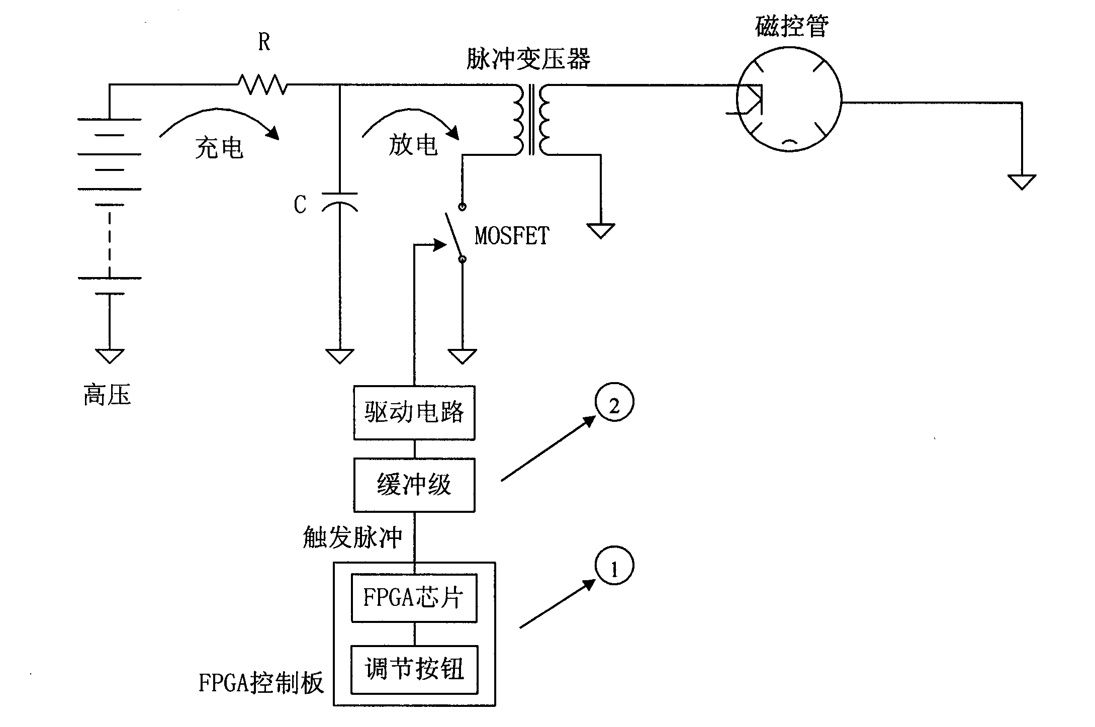
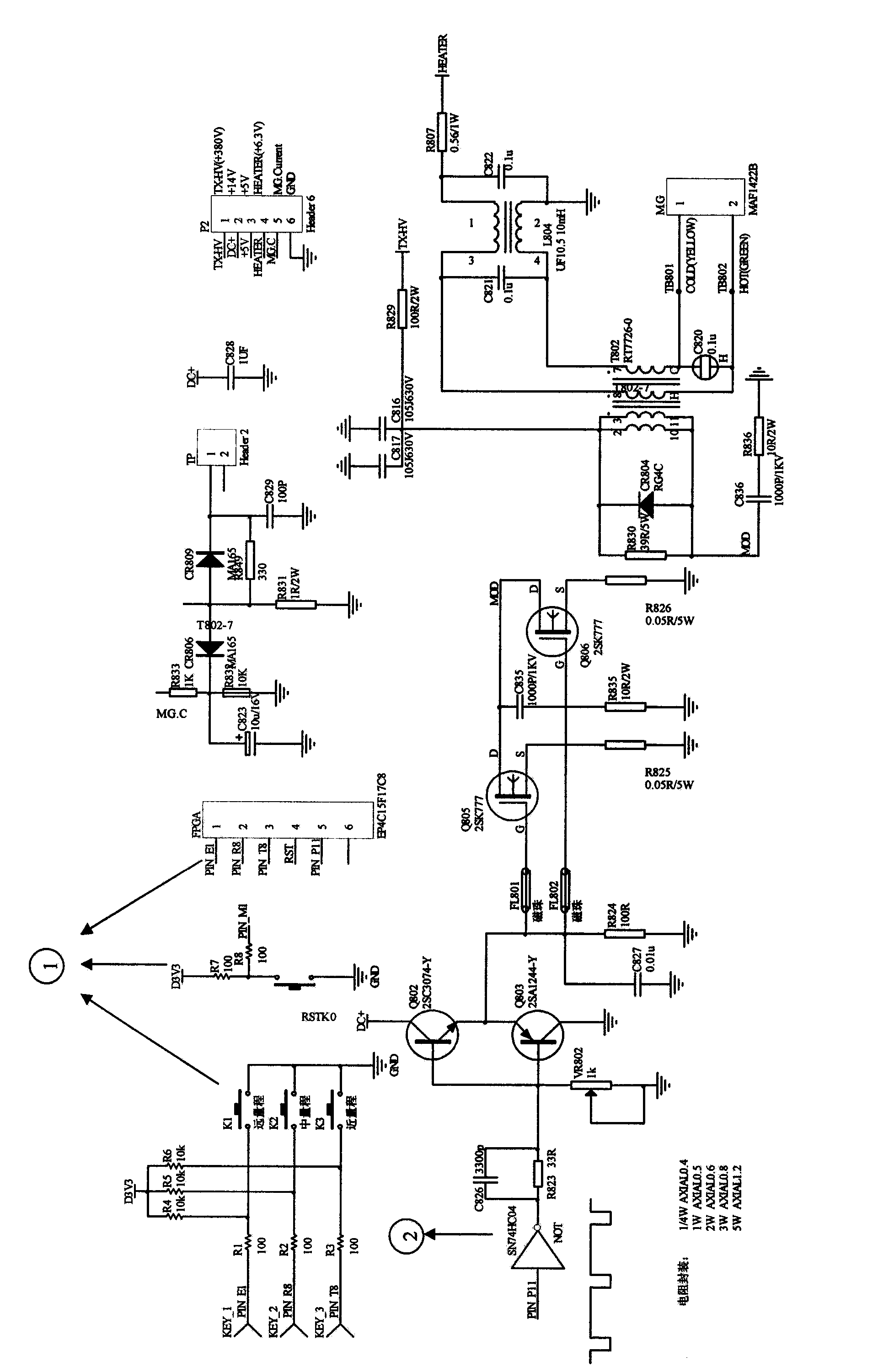
[0037] refer to figure 1 , wherein ① indicated FPGA control board and ② indicated buffer stage circuit two parts are the core of the radar transmitter control method based on FPGA that the present invention proposes. figure 1 The radar transmitter shown uses FET (Field Effect Transistor) as a switch-controlled rigid switch pulse modulator, coupled with a 1:16 pulse transformer, so that the entire modulator works in a low-voltage state. When the magnetron is not working, the high voltage is added to the capacitor C through the resistor R, and when the trigger pulse acts on the MOS-FET, the magnetron is excited to oscillate. The above part is similar to the method used by traditional radar transmitters. The difference between the present invention and the prior art is that FPGA is used as the generator of the trigger pulse, and the trigger pulse is added to the switch tube through the drive circuit after passing through a buffer stage. Control the on-off of the switch tube.

...


PUM


Abstract

The invention discloses a method for implementing a ship-navigation radar transmitting and receiving system. The method includes a transmitting aspect and a receiving aspect. An FPGA (field programmable gate array)-based process for controlling a ship-navigation radar transmitter is provided in the transmitting aspect, trigger pulses are generated via an FPGA, are transmitted through a buffer-stage circuit and a driving circuit and then are boosted to obtain pulsed high voltages by a pulse transformer, the pulsed high voltages are supplied for a magnetron, and radar electromagnetic waves are transmitted by the magnetron at corresponding frequencies. A ship-navigation radar intermediate-frequency digital module which can be directly connected with the FPGA is implemented in the receiving aspect, circuits of a logarithm amplifier, the buffer-stage circuit, an analog-to-digital conversion circuit and the like are integrated via reasonable circuit layout and shielding structures to obtain the module, analog intermediate-frequency signals of a radar radiofrequency receiver can be converted into digital signals by the module, and the digital signals can be outputted to the FPGA by the module. The method has the advantages of large dynamic range, high sensitivity, compact circuits, simplicity in debugging and the like. Besides, owing to the method for implementing the transmitting and receiving system, the ship-navigation radar transmitting and receiving system is compact in design and easy to implement, and the radar cost performance can be improved.

Description

technical field [0001] The invention belongs to the field of radar systems, in particular to the field of ship navigation radar transmitting and receiving subsystems, in particular to a novel and simple method for realizing radar pulse signal transmission and echo signal digital reception. Background technique [0002] Radar is widely used in many fields such as national defense and military, civil aviation control, topographic survey, meteorology, and navigation. In terms of navigation, radars installed on ships for navigation avoidance, ship positioning, and narrow waterway piloting are ship navigation radars, also known as navigation radars. When visibility is low, this type of radar can provide necessary means of observation. Ship navigation radars generally work in the X-band (8-12GHz) or S-band (2-4GHz), and a few work in the C-band (4-8GHz) or Ku-band (12-18GHz). The pulse transmission power is generally several kilowatts to several Between ten kilowatts. [0003] A...

Claims


Application Information

Patent Timeline
Patent Type & Authority Applications(China)
IPC IPC(8): G01S7/282G01S7/34
CPCG01S7/28G01S7/282G01S7/34
Inventor 葛俊祥鲁建彬潘安马志强李家强
Owner 南京信大电子科技有限公司
Learn More