

Distribution type optical fiber vibration detection method and system based on wavelength division multiplexing
A distributed optical fiber and wavelength division multiplexing technology, which is applied to measurement devices, uses wave/particle radiation, and measures ultrasonic/sonic/infrasonic waves, etc., which can solve the problem that the frequency and position information of vibration signals cannot be detected at the same time.
- Summary
- Abstract
- Description
- Claims
- Application Information
AI Technical Summary
Problems solved by technology
Method used
Image


Examples
Embodiment 1
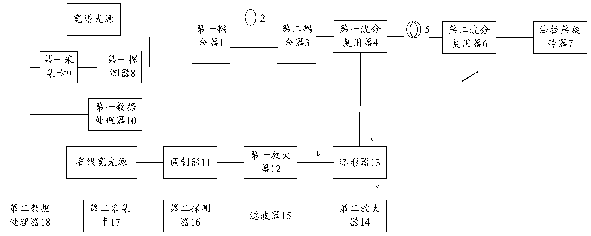
[0022] Please see figure 1 , is the architecture diagram of the distributed optical fiber vibration detection system based on wavelength division multiplexing.
[0023] Wherein, the system specifically includes: an isolator, a first coupler 1, a delay fiber 2, a second coupler 3, a first wavelength division multiplexer 4, a sensing fiber 5, a second wavelength division multiplexer 6, Faraday rotator 7, first detector 8, first acquisition card 9, first data processor 10, modulator 11, first amplifier 12, circulator 13, second amplifier 14, filter 15, second detector 16, a second acquisition card 17, and a second data processor 18.
[0024] The following describes the connection relationship and function of each component.
[0025] Among them, the isolator is used to center wavelength λ 1 Broad-spectrum light source for processing.
[0026] The first coupler 1 is connected to the second coupler 3 through a delay fiber 2 , and the first coupler 1 is also directly connected to...
Embodiment 2
[0045] Please continue to read figure 1 , Sagnac sensor and Φ-OTDR sensor share a sensing fiber.
[0046] The center wavelength is λ 1 The wide-spectrum light source is used as the light source of the Sagnac sensor, and after being split by the first coupler 1, it becomes two beams of light (ie, the first beam and the second beam). Wherein, the first coupler 1 includes but is not limited to a 2×2 coupler with a splitting ratio of 1:1.
[0047] The first light beam enters the second coupler 3 after passing through the delay fiber, and the second light beam directly enters the second coupler 3 without passing through the delay fiber. Wherein, the second coupler 3 includes, but is not limited to, a 2×2 coupler with a splitting ratio of 1:1.
[0048] The main role of the delay fiber is to enhance the non-reciprocal effect in Sagnac.
[0049] The first light beam is transmitted from the second coupler 3, and after passing through the first wavelength division multiplexer 4, the...
PUM
 Abstract
Description
Claims
Application Information