Associated chromatographic method and device

A tomographic device and tomographic image technology, applied in the field of optical imaging, can solve the problems of weakening the correlation between object light path and reference light, reducing imaging quality, etc., and achieve the effects of no radiation hazard, wide application prospects, and low cost

Inactive Publication Date: 2014-12-24
SHANGHAI INST OF OPTICS & FINE MECHANICS CHINESE ACAD OF SCI
View PDF3 Cites 8 Cited by
  • Summary
  • Abstract
  • Description
  • Claims
  • Application Information

AI Technical Summary

Problems solved by technology

The problem is that the resolution of the imaging is the ultrasound resolution
However, the scattering process experienced by light before reac

Method used


Image

  • Associated chromatographic method and device
  • Associated chromatographic method and device
  • Associated chromatographic method and device

Examples


Embodiment 1

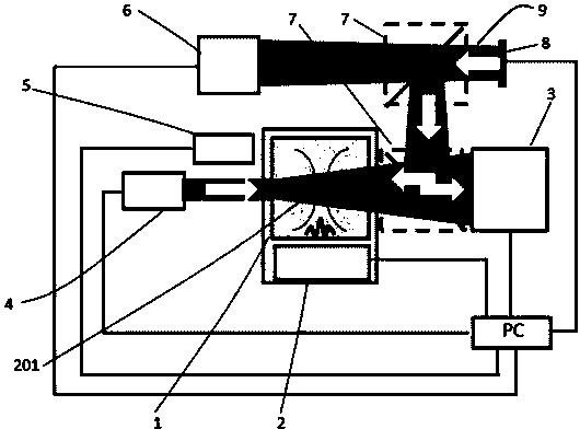
[0059] Such as Figure 10 , wherein the ultrasonic transmitter 2 is composed of an ultrasonic converter 204 , a signal generator 202 and a signal amplifier 203 . Pulsed laser 401 sent by pulsed laser 4 (for example, Coherent passively Q-switched laser FLARE, wavelength range 390nm-800nm) and pulsed ultrasound sent by ultrasonic converter 204 (for example, one or more cycles of 1MHz, one or more cycles of 10MHz) cycles, one or more cycles of 150MHz) act on the sample 1 at the same time, and the PC or the delay generator (not shown in the figure) controls the time delay of the two pulse signals so that the laser and the ultrasound arrive at the ultrasound focus 201 (or more accurately to different positions within the focal point). The ultrasonic transducer is driven by a function generator 202 and a signal amplifier 203 . Outside the sample, the outgoing frequency modulated light 403 is irradiated onto the phase conjugate mirror 3 to be recorded. Subsequently, the thermal li...

Embodiment 2

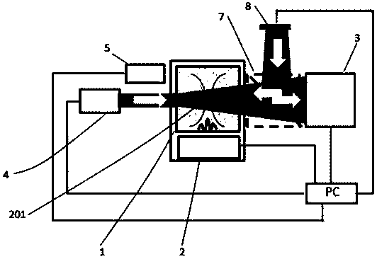
[0060] Embodiment 2: as Figure 11 As shown, using a relatively simplified optical path and detection, the light source 8 uses a computer-controlled SLM or a digital micromirror device DMD (digital micromirror device, referred to as DMD) to reflect laser light (which can be split from the incident light beam 401, or another Laser emission) instead, adjust the distribution of pixels on the SLM or DMD according to the pseudo-random sequence to generate pseudo-thermal light. The outgoing pseudothermal light is reflected by the phase conjugate mirror 3, and the reflected light illuminates the sample 1. The detector 5 detects the light emitted from the sample 1. Since the pseudo-random fluctuation of the pseudo-heat source is known, the light intensity distribution of the reference arm can be calculated, and the two sets of data are correlated by a computer to obtain a tomographic image.


PUM


Abstract

The invention relates to an associated chromatographic method and device. The method comprises the following steps: (1) fixing a sample; (2) emitting a beam of laser by a laser to irradiate the sample and transmitting ultrasound by an ultrasonic transmitter to act on the sample; (3) emitting a beam of object light from a thermal light source or a pseudo-thermal light source, reflecting the light by a phase conjugate mirror to irradiate the sample, spreading the light in the sample, then emitting the light and detecting the emitted light by a light intensity detector to obtain a first group of signal light; (4) emitting another beam of reference light from the thermal light source or the pseudo-thermal source, and detecting by a detector with spatial resolution capability to obtain a second group of signal light, or calculating to obtain the second group of signal light according to the known statistical distribution of the pseudo-thermal source; and (5) performing association operation on the two groups of signals to give out an associated chromatographic image. By adopting the method and the device provided by the invention, an associated image at an ultrasound focus can be obtained. Associated chromatography can obtain an optical image with optical resolution in biological soft tissue in a dynamic and lossless manner.

Description

technical field [0001] The invention relates to optical imaging, in particular to a correlation tomography method and device. Background technique [0002] The time-reversal ultrasound-assisted optical focusing method realizes the dynamic and non-destructive focusing of light into biological soft tissue for the first time. Optical tomography in biological tissue using this method has also received extensive attention, and some articles and patents have disclosed the progress of related research work. Here we take the patent US8450674B2 "Acoustic assisted phase conjugate optical tomography" as an example to briefly analyze the problems existing in the existing technical solutions. [0003] Patent US8450674B2 discloses an optical microscope method and system for performing chromatography on samples embedded with one or more fluorescent media. The system is characterized in that it includes a sample to be tested and a laser, and the laser emitted by the laser is irradiated to ...

Claims


Application Information

Patent Timeline
IPC IPC(8): G01N21/17G01N21/47
Inventor 刘红林韩申生
Owner SHANGHAI INST OF OPTICS & FINE MECHANICS CHINESE ACAD OF SCI
Why Eureka
Try Eureka