Air cooling type hydrogen fuel stand-by power monitoring system
What is Al technical title?
Al technical title is built by PatSnap Al team. It summarizes the technical point description of the patent document.
A backup power supply and monitoring system technology, applied in control/regulation systems, non-electric variable control, and simultaneous control of multiple variables, etc., can solve the problem of not having system backup power, and achieve real-time power backup, safety and reliability. Improve performance and increase the effect of system security monitoring
Active Publication Date: 2014-12-24
BEIJING AZURE HYDROGEN ENERGY TECH
View PDF5 Cites 14 Cited by
Summary
Abstract
Description
Claims
Application Information
AI Technical Summary
This helps you quickly interpret patents by identifying the three key elements:
Problems solved by technology
Method used
Benefits of technology
Problems solved by technology
Usually, the hydrogen fuel backup power supply control system only realizes the detection and control of its core component --- the hydrogen fuel cell module, and does not include the supporting devices (such as hydrogen storage cylinders, installation cabinets) and environmental parameters (such as environmental Temperature and humidity) and environmental safety (such as hydrogen leakage) detection and control, and the general hydrogen fuel backup power control system does not have the calculation of system backup time
Method used
Image
Click on the blue label to locate the original text in one second.
Reading with bidirectional positioning of images and text.
Examples
Embodiment Construction
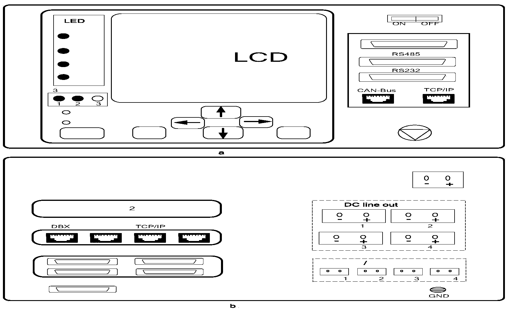
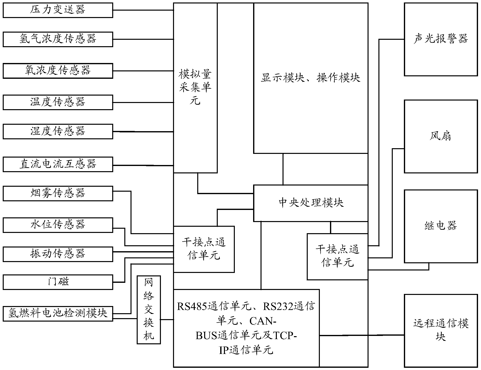
[0036] see figure 1 , figure 1 It is a schematic structural diagram of an air-cooled hydrogen fuel backup power monitoring system according to an embodiment of the present invention.
[0037] Such as figure 1 As shown, pressure transmitter, hydrogen concentration sensor, oxygen concentration sensor, temperature sensor, humidity sensor, DC current transformer are connected to the analog quantity acquisition unit of the controller, smoke sensor, water level sensor, vibration sensor, door sensor, hydrogen fuel cell The detection module is connected to the dry contact communication unit of the controller, the hydrogen fuel cell detection module is connected to the network switch, and the controller is also connected to the network switch, so as to exchange data through the network. The interfaces connecting the hydrogen fuel cell detection module and the controller to the network switch are TCP -IP interface, or TCP-IP communication unit. In one embodiment of the present invent...
PUM
Abstract
The invention discloses an air cooling type hydrogen fuel stand-by power monitoring system which is characterized by comprising a detection element, a controller, a network switch and an actuator. The detection element comprises a pressure transmitter, a hydrogen concentration sensor, an oxygen concentration sensor, a temperature sensor, a humidity sensor, a direct-current transformer, a smoke sensor, a water level sensor, a vibrating sensor, a door magnet and a hydrogen fuel cell detecting module, wherein the pressure transmitter, the hydrogen concentration sensor, the oxygen concentration sensor, the temperature sensor, the humidity sensor, the direct-current transformer, the smoke sensor, the water level sensor, the vibrating sensor, the door magnet and the hydrogen fuel cell detecting module are connected with the controller so that detected parameters of a hydrogen fuel standby power source and a cabinet can be transmitted to the controller. The controller can transmit data to an upper computer through the network switch or a serial port. The controller processes the data. When an alarm needs to be given, alarm information is sent out, or the actuator is controlled to execute the corresponding movement when it is judged that the parameters are changed.
Description
technical field [0001] The invention relates to the field of hydrogen fuel backup power supply, in particular to an air-cooled hydrogen fuel backup power monitoring system. Background technique [0002] The air-cooled hydrogen fuel backup power system is a backup power system that uses proton exchange membrane fuel cell technology, uses hydrogen and oxygen in the air, and generates electricity through electrochemical reactions. It can be widely used in communication operator base stations, power substation communication rooms, bank data Industries such as computer rooms that require safe and reliable backup power protection for electric power. Due to its strong load capacity, high power density, low noise, no pollution emissions, and long-term power supply, the hydrogen fuel backup power supply technology can overcome the shortcomings of the current traditional oil engine and lead-acid battery, and is especially suitable for population density applications. Therefore, hydro...
Claims
Application Information
Patent Timeline
Application Date:The date an application was filed.
Publication Date:The date a patent or application was officially published.
First Publication Date:The earliest publication date of a patent with the same application number.
Issue Date:Publication date of the patent grant document.
PCT Entry Date:The Entry date of PCT National Phase.
Estimated Expiry Date:The statutory expiry date of a patent right according to the Patent Law, and it is the longest term of protection that the patent right can achieve without the termination of the patent right due to other reasons(Term extension factor has been taken into account ).
Invalid Date:Actual expiry date is based on effective date or publication date of legal transaction data of invalid patent.