Efficient cooling LED backlight device

An LED backlight and LED lamp technology, which is applied to light sources, lighting devices, point light sources, etc., can solve the problems of poor thermal conductivity of the insulating resin layer 133, cannot meet the heat dissipation requirements of the backlight unit, and reduce the LED lamp 11, etc., so as to achieve enhanced Effects of radiation heat transfer capability, extended life, and improved reliability

Inactive Publication Date: 2015-01-07
中航华东光电有限公司
View PDF5 Cites 9 Cited by
  • Summary
  • Abstract
  • Description
  • Claims
  • Application Information

AI Technical Summary

Problems solved by technology

[0007] Although the above-mentioned way of dissipating heat from the lower surface of the backlight panel can reduce the junction temperature of the LED lamp 11 to a certain extent, if Figure 5 As shown, the heat transfer from the upper surface to the lower surface of the PCB lamp board 13 needs to pass through multiple copper layers 132 and insulating resin layers 133, and the thermal conductivity of the insulating resin layer 133 is poor, so from the electrode 114 of the LED lamp 11 to the PCB The thermal resistance of the lower surface of the lamp board is often much greater than the thermal resistance to the upper surface of the PCB lamp board
If only heat dissipation from the lower surface of the PCB lamp board 13 is considered, for some PCB lamp boards with high power, high heat generation, or poor thermal conductivity, it cannot meet the heat dissipation requirements of the backlight unit.

Method used


Image

  • Efficient cooling LED backlight device
  • Efficient cooling LED backlight device
  • Efficient cooling LED backlight device

Examples


Embodiment 1

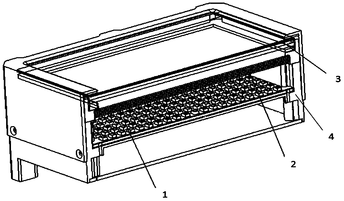
[0027] Such as Figure 6 As shown, a high-efficiency heat dissipation LED backlight device includes an LED lamp 11, a PCB lamp board 13, a heat-conducting material 14, a white reflector 12, and a backlight cavity structure 43. The LED lamp 11 is welded on the PCB lamp board 13, and the white The reflective sheet 12 is pasted on the inner wall of the backlight cavity structure 43 to effectively reduce the absorption of light by the backlight cavity and improve the light utilization rate of the backlight cavity. The heat-conducting material 14 is filled between the PCB lamp board 13 and the backlight cavity structure 43, The thermally conductive material 14 is thermally conductive silicone grease or a thermally conductive gasket, which can better conduct the heat on the upper surface of the PCB lamp board 1313 to the backlight cavity structure 43. On the lamp board 13, there are holes corresponding to the position of the LED lamp 11, so that the PCB lamp board 13 can be easily l...

Embodiment 2

[0029] Such as Figure 7As shown, a high-efficiency heat dissipation LED backlight device includes an LED lamp 11, a PCB lamp board 13, a heat-conducting material 14, a white reflector 12, and a backlight cavity structure 43. The LED lamp 11 is welded on the PCB lamp board 13, and the white The reflective sheet 12 is pasted on the inner wall of the backlight cavity structure 43 to effectively reduce the absorption of light by the backlight cavity and improve the light utilization rate of the backlight cavity. The heat-conducting material 14 is filled between the PCB lamp board 13 and the backlight cavity structure 43, The thermally conductive material 14 is thermally conductive silicone grease or a thermally conductive gasket, which can better conduct the heat on the upper surface of the PCB lamp board 13 to the backlight cavity structure 43 and the structural backplane 44, and the backlight cavity structure 43 and the white reflector 12 There are a plurality of openings corre...


PUM

PropertyMeasurementUnit
luminanceaaaaaaaaaa

Abstract

The invention discloses an efficient cooling LED backlight device. The efficient cooling LED backlight device comprises an LED lamp, a PCB lamp panel, a heat conducting material, a white reflective sheet and a backlight cavity structural part; holes corresponding to LED lamps on the PCB lamp panel in position are formed in the backlight cavity structural part and the white reflective sheet; the PCB lamp panel is mounted on the outer side of the bottom surface of the backlight cavity structural part; the LED lamps extends into the backlight cavity structural part through the holes; the efficient cooling LED backlight device further comprises a structural back panel, a graphene thin film and a thermal radiation enhancement material, wherein the structural back panel is arranged on the lower surface of the PCB lamp panel, the graphene thin film is arranged between the backlight cavity structural part and the PCB lamp panel and the thermal radiation enhancement material is formed on the outer wall of the backlight cavity structural part by coating. Compared with the prior art, the efficient cooling LED backlight device has the advantages of enhancing the radiative heat transfer capacity of the backlight structure, improving the heat dissipation capacity of the whole backlight system and reducing the junction temperatures of the LED lamps, and furthermore, improving the reliability of the LED backlight, prolonging the service life of the LED backlight and improving the luminous efficiency.

Description

technical field [0001] The invention relates to a heat dissipation device for electrical components, in particular to an efficient heat dissipation LED backlight source device. Background technique [0002] In recent years, liquid crystal displays (LCDs) have become more and more prominent in terms of size, weight, and power consumption, and have gradually replaced cathode ray tube (CRT) displays and become mainstream display devices. The LCD panel itself does not emit light and must rely on light from the backlight. Such as figure 1 As shown, the liquid crystal display module using a direct-lit backlight unit is composed of a liquid crystal panel 3, an optical film 2, a backlight unit 1, a mechanical structure system 4 and a driving circuit. Under the support of the mechanical structure and the fixed protection, the light is emitted by the backlight system under the control of the drive circuit, and a uniform backlight with a certain brightness is formed through the unifo...

Claims


Application Information

Patent Timeline
Patent Type & Authority Applications(China)
IPC IPC(8): G02F1/13357F21V29/00F21Y101/02
CPCF21Y2101/00G02F1/1336G02F1/133628
Inventor 李正荣李拓辉唐景坤吴丽徐立国
Owner 中航华东光电有限公司
Why Eureka
Try Eureka