Magnetic field orientation three-dimensional printing anisotropic bonded permanent magnet and preparation method thereof

A technology of magnetocrystalline anisotropy and anisotropy, which is used in the manufacture of inductors/transformers/magnets, electrical components, circuits, etc., and can solve problems that affect the arrangement and forming of droplets, complex process, and inability to achieve anisotropic bonding. Magnet 3D printing and other problems, to achieve the effect of eliminating the magnetic interaction force

Active Publication Date: 2015-01-07
CENT IRON & STEEL RES INST
View PDF5 Cites 26 Cited by
  • Summary
  • Abstract
  • Description
  • Claims
  • Application Information

AI Technical Summary

Problems solved by technology

Since the demagnetized powder still has weak magnetism, which affects the arrangement and formation of droplets, the 3D printing of anisotropic bonded magnets cannot be realized.
In the prior art, Chinese Invention Patent Application

Method used


Image

  • Magnetic field orientation three-dimensional printing anisotropic bonded permanent magnet and preparation method thereof
  • Magnetic field orientation three-dimensional printing anisotropic bonded permanent magnet and preparation method thereof
  • Magnetic field orientation three-dimensional printing anisotropic bonded permanent magnet and preparation method thereof

Examples


preparation example Construction

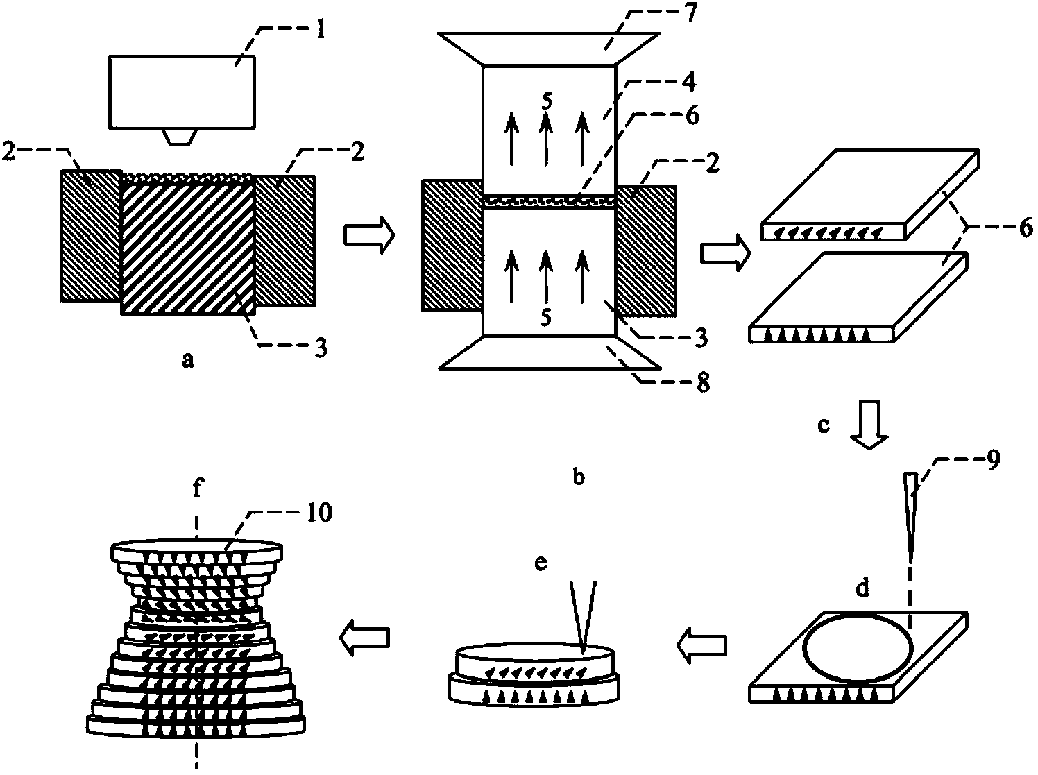
[0048] Such as figure 2 As shown, the preparation method of the magnetic field orientation three-dimensional printing anisotropic bonded magnet of the present invention comprises the following steps:

[0049] a) Powder loading: The magnet powder with magnetic crystal anisotropy is crushed by coarse crushing, jet milling or ball milling to a powder with an average particle size of 1-5um, and then mixed evenly with a binder. The binder is polyamide, One of unsaturated polyester and acrylate, mercaptan, ethylene copolymer, epoxy resin or metal tin; the volume ratio of powder to binder is 99.5:0.5~0.5:99.5; the mixed powder is supplied by The system is added to the mold to form an evenly distributed powder layer;

[0050] b) Orientation forming: the upper and lower pressing heads move the pre-pressed powder in opposite directions, and a magnetic field is applied through the upper and lower pole heads. The magnetic field strength is 0-2.2 tesla, so that the magnetic powder is ori...

Embodiment 1

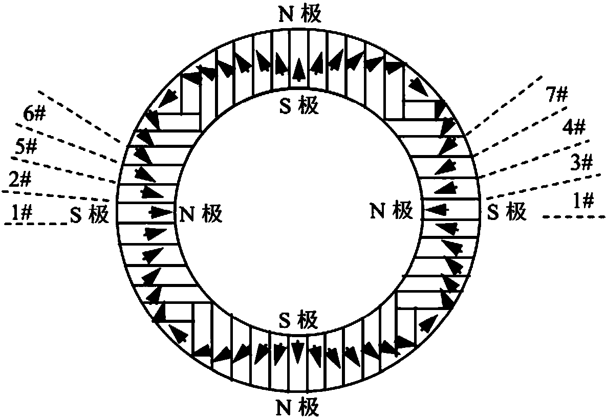
[0057] A four-pole radiation-oriented bonded permanent magnet ring was prepared by three-dimensional printing.

[0058] Such as figure 2 As shown, the three-dimensional printing molding process of embodiment 1 comprises the following steps:

[0059] a) Powder loading: Nd with magnetocrystalline anisotropy 2 Fe 14 B Magnet powder, crushed by coarse crushing, jet milling or ball milling to a powder with an average particle size of 3um, mixed with thermosetting epoxy resin at a volume ratio of 95:5; the mixed powder is added to the mold by the feeding system , forming a powder layer with a thickness of 10um and uniform distribution;

[0060] b) Orientation molding: the upper and lower pressing heads move the pre-pressed powder in opposite directions, and a magnetic field is applied through the upper and lower pole heads. The magnetic field strength is 1.8 Tesla, so that the magnetic powder is oriented along the direction of the magnetic field, and then pressed to form a speci...

Embodiment 2

[0067] A composite permanent magnetic gradient functional material block was prepared by a three-dimensional printing process.

[0068] Such as figure 2 As shown, the three-dimensional printing molding process of embodiment 2 comprises the following steps:

[0069] a) Powder loading: Sm with magnetocrystalline anisotropy 2 co 17 The powder crushed to an average particle size of 3um by coarse crushing, jet milling or ball milling is mixed evenly with thermosetting epoxy resin at a volume ratio of 95:5; the mixed powder is added to the molding mold by the feeding system, Form a powder layer with a thickness of 15um and uniform distribution;

[0070] b) Orientation forming: the upper and lower indenters move towards each other, pre-press the powder, apply a magnetic field through the upper and lower pole heads, the magnetic field strength is 2.2 Tesla, orient the magnetic powder along the direction of the magnetic field, and then carry out molding and pressing to form a orie...


PUM


Abstract

The invention relates to the technical field of rare earth permanent magnetic materials, in particular to a magnetic field orientation three-dimensional printing anisotropic bonded permanent magnet and a preparation method thereof. The magnetic field orientation three-dimensional printing anisotropic bonded permanent magnet, adopts magnet powder having magnetocrystalline anisotropy, comprises one or a plurality of anisotropic neodymium iron boron magnetic powder, samarium cobalt magnetic powder and samarium iron nitrogen powder and is a semi-continuous or continuous orientation changed anisotropic bonded permanent magnet. The magnetic field orientation three-dimensional printing anisotropic bonded permanent magnet is prepared by the following steps of powder filling, orienting and forming into sheet layers, thermal demagnetizing, cutting the sheet layers into required-shaped unit sheet layers, stacking and solidifying the unit sheet layers layer by layer and magnetizing. According to the magnetic field orientation three-dimensional printing anisotropic bonded permanent magnet and the preparation method thereof, preparation of the three-dimensional printing anisotropic bonded permanent magnet is achieved, adjustment of the orientation and the order degree of powder in the sheet layers are achieved by adjusting the magnetic field direction and or the magnetic field strength, the defect that orientation of the traditional bonded permanent magnet cannot be changed is overcame, and continuous or semi-continuous change of magnetic orientation in the same three-dimensional entity is achieved.

Description

technical field [0001] The invention relates to the technical field of rare earth permanent magnet materials, in particular to a three-dimensionally printed anisotropic bonded magnet with magnetic field orientation and a preparation method thereof. Background technique [0002] In recent years, rapid prototyping technologies such as "additive manufacturing" and "three-dimensional printing" have developed rapidly, and combined with traditional manufacturing technologies, from the initial rapid prototyping that is only suitable for raw materials such as wood, resin, and plastic, to metal, high-temperature A new technology approach for low-cost, short-cycle, near-net-shape manufacturing of large and complex structural parts such as alloys. This technology is a revolutionary digital forming technology that can greatly improve production efficiency, reduce costs, and realize product diversification. 3D printing technology presents the physical world in a digital way, and becomes...

Claims


Application Information

Patent Timeline
IPC IPC(8): H01F41/02
Inventor 李卫冯海波李安华朱明刚赵扬
Owner CENT IRON & STEEL RES INST
Why Eureka
Try Eureka