Preparing and compensating method for temperature drift self-compensating SOI pressure sensor

A pressure sensor and self-compensation technology, applied in the field of MEMS sensors, can solve the problems of limiting the development of the sensor industry, affecting the accuracy of the sensor, poor consistency, etc., to achieve the effect of improving stability and operating temperature range, good product consistency, and high sensitivity

Active Publication Date: 2015-01-14
无锡芯感智半导体有限公司
View PDF7 Cites 7 Cited by
  • Summary
  • Abstract
  • Description
  • Claims
  • Application Information

AI Technical Summary

Problems solved by technology

[0005] In addition, since the resistor is a temperature-sensitive device, the zero point and sensitivity of the pressure sensor before compensation will change with the change of temperature, which greatly affects the accuracy of the sensor, and it is usually compensated for temperature drift
At present, pressure sensor compensation is divided into two types: hardware compensation and software compensation. The former requires a lot of manpower to test the temperature drift of each chip before compensation within the operating temperature range, and then select different devices, such as diodes and thermistors. The consistency is poor and the workload is heavy; and the software compensation cost is high. At present, most of the domestic compensation is for imported ASIC chips. The high price also limits the development of the domestic sensor industry.

Method used


Image

  • Preparing and compensating method for temperature drift self-compensating SOI pressure sensor
  • Preparing and compensating method for temperature drift self-compensating SOI pressure sensor
  • Preparing and compensating method for temperature drift self-compensating SOI pressure sensor

Examples


Embodiment Construction

[0026] The present invention will be further described below in conjunction with specific drawings and embodiments.

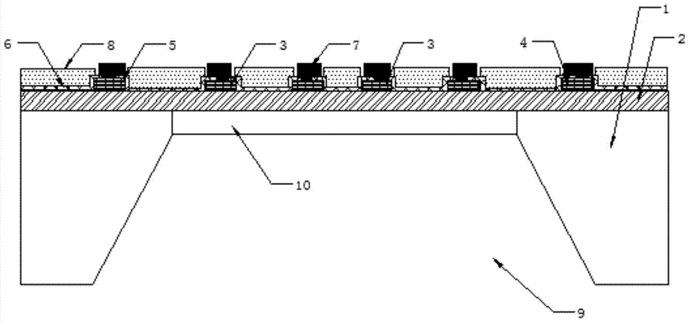
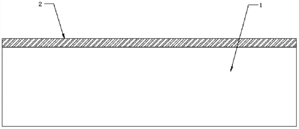
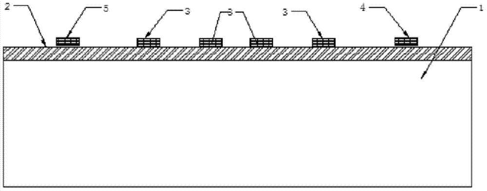
[0027] like figure 1 Shown: In order to improve the measurement accuracy and temperature adaptation range of the pressure sensor, the pressure sensor includes an SOI substrate, on which a conductive material is deposited and a bridge resistance 3 for configuring a Wheatstone bridge is obtained, And in order to reduce the influence of temperature drift, a compensation resistor is provided on the SOI substrate, and the compensation resistor includes a constant voltage power supply compensation resistor 4 or a constant current power supply compensation resistor 5, and a constant voltage power supply compensation resistor 4 is set on the SOI substrate at the same time and the constant current power supply compensation resistor 5, the constant voltage power supply compensation resistor 4 or the constant current power supply compensation resistor 5 can be selected ac...


PUM


Abstract

The invention relates to a preparing and compensating method for a temperature drift self-compensating SOI pressure sensor. The temperature drift self-compensating SOI pressure sensor comprises an SOI substrate, a bridge circuit resistor used for being configured into a wheatstone bridge is arranged on the SOI substrate, a compensating resistor used for conducting temperature compensation on the wheatstone bridge is arranged on the part, corresponding to the surface provided with the bridge circuit resistor, of the SOI substrate, and interconnection leads electrically connected are arranged on the compensation resistor and the bridge circuit resistor. The compensation resistor and the bridge circuit resistor are isolated through an insulation isolating layer and a passivation layer, the insulation isolating layer covers the SOI substrate, and the passivation layer covers the insulation isolating layer. The part, corresponding to the other side provided with the bridge circuit resistor, of the SOI substrate is etched to form a pressure cavity and a pressure sensitive membrane, and the pressure cavity and the pressure sensitive membrane are located under the bridge circuit resistor. The temperature drift self-compensating SOI pressure sensor is compact in structure, capable of achieving temperature drift self-compensation and reducing cost, high in stability, good in consistency, suitable for mass production, wide in application range, safe and reliable.

Description

[0001] The present invention is a divisional application of a patent application filed on November 23, 2011 with the application number 201110375349.X and the invention name "Temperature Drift Self-Compensating SOI Pressure Sensor". technical field [0002] The invention relates to a pressure sensor, in particular to a temperature drift self-compensating SOI pressure sensor, which belongs to the technical field of MEMS sensors. Background technique [0003] The pressure sensor manufactured by using the piezoresistive effect of silicon is to use the ion implantation and diffusion process in the integrated circuit process to form a group of diffusion resistors with almost equal resistance values ​​on the surface of the silicon wafer, and form metal interconnections between the resistors, which are connected into Whiskers. power bridge. When the elastic sensitive diaphragm deforms under the action of external pressure to generate stress, the bridge resistance on it changes acc...

Claims


Application Information

Patent Timeline
Patent Type & Authority Applications(China)
IPC IPC(8): G01L19/04G01L9/04
Inventor 刘同庆
Owner 无锡芯感智半导体有限公司
Why Eureka
Try Eureka