A Flow Fluorescence Collection Optical System

An optical system and flow fluorescence technology, applied in the field of cell analysis, can solve the problems of small fiber spacing, increased lens design, and high difficulty in alignment and adjustment

Active Publication Date: 2017-01-04
BOAO BIOLOGICAL CO LTD +1
View PDF6 Cites 3 Cited by
  • Summary
  • Abstract
  • Description
  • Claims
  • Application Information

AI Technical Summary

Problems solved by technology

[0004] Scheme 1 Although the reflector scheme is simple in structure, the boundary dimension accuracy of the mirror edge is very poor. At the same time, it is easy to introduce fluorescence crosstalk excited by different lasers or too much stray light into the fluorescence receiving channel, which affects the fluorescence receiving bandpass filter. The requirements for coating parameters are very high. For example, it is generally required to have an OD (Optical Density) of 6 or more outside the passband to prevent stray light, so the difficulty and cost of coating the filter will increase a lot. At the same time, the problem of crosstalk still exists, resulting in measurement The inaccuracy and the reduction of fluorescence detection sensitivity of important indicators of flow cytometry
[0005] Option 2 The optical fiber receiving solution is currently adopted by many streamers. It can effectively solve the problems of stray light and fluorescent crosstalk, but it has many disadvantages. 1. The fiber coupling efficiency is low. To improve the coupling efficiency, complex aspheric multi-chip Coupling lens design, which will inevitably lead to a substantial increase in cost. 2. The optical fiber has a certain size envelope, and the distance between the optical fibers cannot be made very small. This requires that the magnification of the fluorescence collection lens be increased while the aberration is small enough, which is also for the lens. The design increases the difficulty of
At the same time, it is relatively difficult to align and adjust the optical fiber
[0006] Therefore, how to solve the problems of high cost, high difficulty in alignment and adjustment, and inaccurate measurement of the fluorescence collecting optical system in the prior art has become an important technical problem to be solved by those skilled in the art.

Method used


Image

  • A Flow Fluorescence Collection Optical System
  • A Flow Fluorescence Collection Optical System

Examples


Embodiment Construction

[0026] The specific embodiment provides a flow-type fluorescence collection optical system, which has low cost, compact structure, easy assembly and adjustment, and high measurement accuracy.

[0027] The following will clearly and completely describe the technical solutions in the embodiments of the present invention with reference to the accompanying drawings in the embodiments of the present invention. Obviously, the described embodiments are only some, not all, embodiments of the present invention. Based on the embodiments of the present invention, all other embodiments obtained by persons of ordinary skill in the art without making creative efforts belong to the protection scope of the present invention.

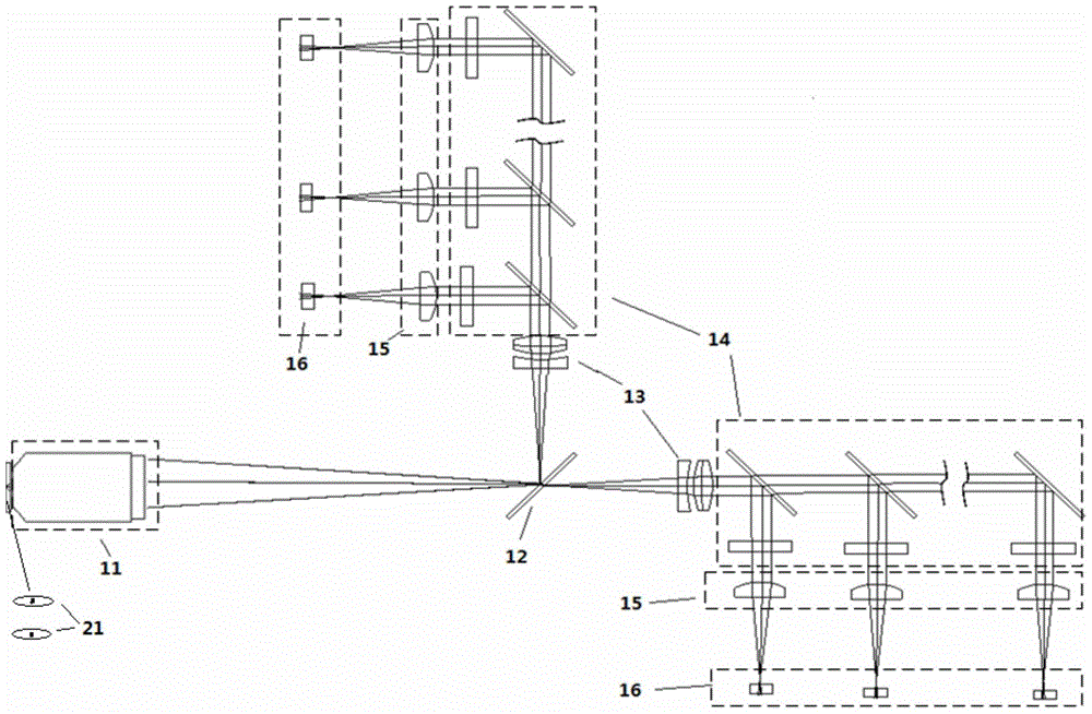
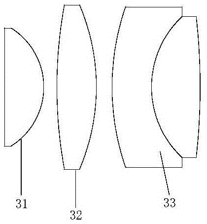
[0028] Please refer to figure 1 and figure 2 , the flow fluorescence collection optical system provided in this specific embodiment includes:

[0029] The fluorescence collecting lens 11 is used to amplify the fluorescence generated by the sample 21 excited by a vari...


PUM

PropertyMeasurementUnit
thicknessaaaaaaaaaa
thicknessaaaaaaaaaa

Abstract

The invention discloses a flow fluorescence collecting optical system. The flow fluorescence collecting optical system comprises a fluorescence collecting lens, a micro beam splitting lens, a plurality of achromatism collimating lenses, a plurality of multicolor lens light filter sets, a plurality of focusing lenses and a plurality of detectors, wherein the fluorescence collecting lens is used for amplifying fluorescence generated by exciting a sample by virtue of a plurality of different laser beams as a plurality of fluorescence image points with gaps which are formed between the fluorescence image points; the fluorescence image points formed by amplification of the fluorescence collecting lens irradiates the micro beam splitting lens; the micro beam splitting lens is used for splitting light and removing stray light of the plurality of fluorescence image points; all the beams of fluorescence image points split by the micro beam splitting lens are processed by achromatism by virtue of at least one achromatism collimating lens; all the beams of fluorescence image points processed by achromatism are filtered by the multicolor lens light filter sets; all the beams of fluorescence image points filtered by the multicolor lens light filter sets are focued to the detectors by virtue of the focusing lens. The flow fluorescence collecting optical system is relatively low in cost, compact in structure, easy to mount and debug and high in measurement accuracy.

Description

technical field [0001] The invention relates to the technical field of cell analysis, in particular to a flow fluorescence collection optical system. Background technique [0002] Flow cytometry and flow cytometry are a detection method for quantitative analysis and sorting of single cells or other biological particles at the functional level. Several parameters were measured in . The detection principle is: the laser beam is irradiated on the single-cell sample flow after being shaped, and the cells passing through the detection area in turn generate weak fluorescence under the irradiation of the laser beam, and then collect as much fluorescence signal as possible through the fluorescence collection lens, the numerical aperture The larger the size, the stronger the fluorescence signal collected, the higher the fluorescence detection performance of the instrument, and then the fluorescence is divided into wavelength regions through collimating lens, dichroic mirror and band...

Claims


Application Information

Patent Timeline
Patent Type & Authority Patents(China)
IPC IPC(8): G01N15/10G01N21/64
Inventor 安栋梁梅丹阳阳巍王东邢婉丽
Owner BOAO BIOLOGICAL CO LTD
Why Eureka
Try Eureka