A nitriding furnace system

A technology of nitriding furnace and nitrogen gas, which is applied in the field of nitriding furnace system and ferroalloy nitriding furnace, can solve the problems of inability to realize continuous production, unstable nitrogen content of products, long production cycle and low efficiency, and facilitate large-scale promotion The use, the overall structure design is ingenious, and the production process is compact

Active Publication Date: 2017-07-18
江苏江南铁合金有限公司 +1
View PDF3 Cites 0 Cited by
  • Summary
  • Abstract
  • Description
  • Claims
  • Application Information

AI Technical Summary

Problems solved by technology

At present, there are two main iron alloy nitriding processes for domestic industrialization: normal pressure nitriding method and pre-vacuum pressure nitriding method. No matter which method has some problems, 1) in the prior art, in order to prevent the oxidation of iron nitride alloy, The high-temperature finished product after the nitriding reaction must be sealed and cooled before it can be released from the furnace. The current cooling technology mainly adopts the method of cooling with the furnace or forced cooling on the outer wall of the reaction tank. Both methods waste the heat energy of the product and reduce the cooling efficiency; 2) Continuous production is basically impossible in the existing technology, so the production cycle is long and the efficiency is low; 3) The heating of the metal material in the prior art is single-sided heating, upper radiation or heating on the outer circumference of the cylinder, so the thickness of the material is too thick. Causes uneven heating temperature, resulting in unstable nitrogen content of the product

Method used


Image

  • A nitriding furnace system
  • A nitriding furnace system
  • A nitriding furnace system

Examples


Embodiment 1

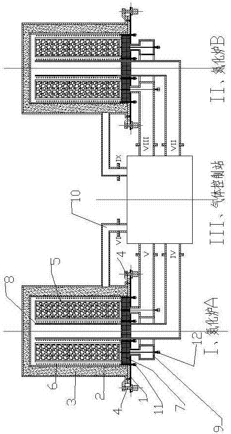
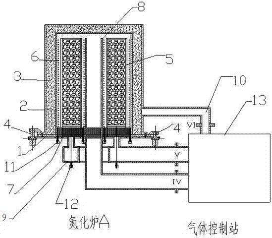
[0028] Embodiment 1: see figure 1 , figure 2 , a nitriding furnace system, the nitriding furnace system includes two nitriding furnaces, i.e. nitriding furnace A and nitriding furnace B, the nitriding furnace A and nitriding furnace B are connected to a gas control station 13 , the structure of nitriding furnace A and nitriding furnace B is exactly the same in this technical scheme, and in specific application, the structure of the first nitriding furnace and the second nitriding furnace are not necessarily identical; The nitriding furnace includes nitriding furnace Furnace base 1, material basket 5, liner 2, central air duct 8, heat preservation shell 3, the material basket 5 is hoisted on the base 1, the liner 2 and heat preservation shell 3 are fixedly connected by locking device 4 On the base 1, the central air duct 8 is arranged in the middle of the nitriding furnace A; wherein the material frame 5 is provided with manganese nitride, the heat preservation shell 3 is arr...

Embodiment 2

[0029] Example 2: see figure 1 , figure 2 , Figure 5 , as an improvement of the present invention, a heat-insulating breathable brick 7 is arranged between the base 1 and the material frame 5, and the thickness of the heat-insulated breathable brick 7 is 150-300mm, which can be selected according to the actual situation, preferably 180-260mm, through the 90-degree rotating hydraulic cylinder locking device 4, the inner tank 2 and the outer shell 13 are fixed on the nitriding furnace base 1, and the heat in the material frame 5 passes through the breathable heat insulating brick 7 and enters the return air ring pipe 9 , and then reach the gas control station for heat conversion and transfer. On the one hand, the breathable heat insulation brick 7 blocks heat conduction during the nitriding reaction, and on the other hand, it can exchange the heat inside the nitriding furnace with the cold material when cooling after the nitriding reaction. This system makes full use of the ...

Embodiment 3

[0030] Embodiment 3: see figure 1 , figure 2 , as an improvement of the present invention, a nitrogen pressure balance pipe 10 is also connected to the insulated casing of the nitriding furnace, one end of the nitrogen pressure balance pipe is connected to the nitriding furnace, and the other end is connected to the gas control station 13 through a balance pipe interface. Connection, the nitrogen pressure balance pipe is a metal hose. The rest of the structures and advantages are exactly the same as in Embodiment 1.


PUM

PropertyMeasurementUnit
thicknessaaaaaaaaaa

Abstract

The invention relates to a nitriding furnace system, which comprises a first nitriding furnace and a second nitriding furnace, and a gas control station is connected between the first nitriding furnace and the second nitriding furnace. The first nitriding furnace includes a base, a material basket, an inner tank, a central air duct, and a thermal insulation shell, the material basket is hoisted on the base, and the inner tank and the thermal insulation shell are fixedly connected to the base through a locking device Above, the central air duct is arranged in the middle of the first nitriding furnace. The beneficial effects of the present invention are as follows: 1) The continuous production of iron nitride alloys is realized by switching between two nitriding furnaces, and the efficiency is greatly improved; 2) The heat exchange system is adopted to make full use of the waste heat of materials, and to speed up the cooling speed, which is both environmentally friendly and Economical; 3) The method of heating the material on both sides increases the amount of material added in a single batch, improving the efficiency and the stability of the nitrogen content of the product; 4) The overall structure design is ingenious, and the entire technical solution occupies a small area and is low in cost , which is convenient for large-scale promotion and use.

Description

technical field [0001] The invention relates to an iron alloy nitriding furnace, in particular to a nitriding furnace system, which belongs to the technical field of mechanical equipment. Background technique [0002] Nitrogen is an austenite stabilizing element and has the function of delaying the precipitation of carbides. It can improve the strength and corrosion resistance of steel. It is considered to be one of the most valuable new materials for research and development. Therefore, the production process of high nitrogen steel Research and development has become the focus of attention and development of all countries. The most ideal way to produce high-nitrogen steel is to add nitrogen-containing iron alloys. At present, there are two main iron alloy nitriding processes for domestic industrialization: normal pressure nitriding method and pre-vacuum pressure nitriding method. No matter which method has some problems, 1) in the prior art, in order to prevent the oxidati...

Claims


Application Information

Patent Timeline
Patent Type & Authority Patents(China)
IPC IPC(8): C23C8/26F27D17/00
Inventor 朱翔鹰翟玉春梅泽锋梅平林一飞
Owner 江苏江南铁合金有限公司
Why Eureka
Try Eureka