Infrared beam control chip based on electronically controlled liquid crystal infrared diverging planar microcylindrical mirror

A beam steering, infrared technology, applied in instruments, optics, static indicators, etc., can solve the problems of strong light leakage, long state transition time, low extinction ratio in the hole, etc., and achieve rapid shaping and modulation, rapid construction and adjustment. Variable, flexible control effects

Active Publication Date: 2017-02-15
HUAZHONG UNIV OF SCI & TECH
View PDF6 Cites 0 Cited by
  • Summary
  • Abstract
  • Description
  • Claims
  • Application Information

AI Technical Summary

Problems solved by technology

[0003] The typical methods for constructing the infrared light field of the micro-rectangular light-hole array that have been widely used at present include: (1) Obtaining the light field of the micro-rectangular light-hole array with a fixed structural size through a conventional concave refracting lens with a fixed surface relief profile, and the micro-rectangular light hole array The shape, width, extinction ratio and array arrangement of the rectangular optical holes are all cured; (2) The light field of the far-field micro-rectangular optical hole array is obtained through the diffraction phase structure based on the wavefront adjustment. The constructed micro-rectangular light hole has poor pattern regularity, blurred boundary and low extinction ratio in the hole, and shows different structural sizes with the change of diffraction order; (3) The micro-rectangular light hole array constructed by multi-beam interference The microhole pattern of the field is approximately linear, the boundary is blurred, and the extinction ratio in the hole is low, and it does not have the ability to finely adjust the size and shape of the microhole structure; (4) The microrectangular light is obtained by setting a special graphic structure in the optical system The hole array light field method is constrained by the more obvious intrinsic diffraction limit of the infrared optical system. On the micron scale, the boundaries of the micro-rectangular light holes are blurred, and there is strong light leakage in the holes and the micro-rectangular light cannot be adjusted. (5) At present, in terms of finely adjusting the aperture width of the arrayed micro-rectangular optical apertures and reducing light leakage in the apertures, it is necessary to use two or even multiple sets of arrayed microlenses arranged in cascade. Due to the slow response, long state transition time and large inertia, relatively complex auxiliary devices need to be configured. Due to the intrinsic continuity of mechanical motion, it is impossible to perform arbitrary optical state cut-in or jump, and it is difficult to flexibly access infrared In the optical path or coupled with other infrared optical optomechanical structures

Method used


Image

  • Infrared beam control chip based on electronically controlled liquid crystal infrared diverging planar microcylindrical mirror
  • Infrared beam control chip based on electronically controlled liquid crystal infrared diverging planar microcylindrical mirror
  • Infrared beam control chip based on electronically controlled liquid crystal infrared diverging planar microcylindrical mirror

Examples


Embodiment Construction

[0024] In order to make the object, technical solution and advantages of the present invention clearer, the present invention will be further described in detail below in conjunction with the accompanying drawings and embodiments. It should be understood that the specific embodiments described here are only used to explain the present invention, not to limit the present invention. In addition, the technical features involved in the various embodiments of the present invention described below can be combined with each other as long as they do not constitute a conflict with each other.

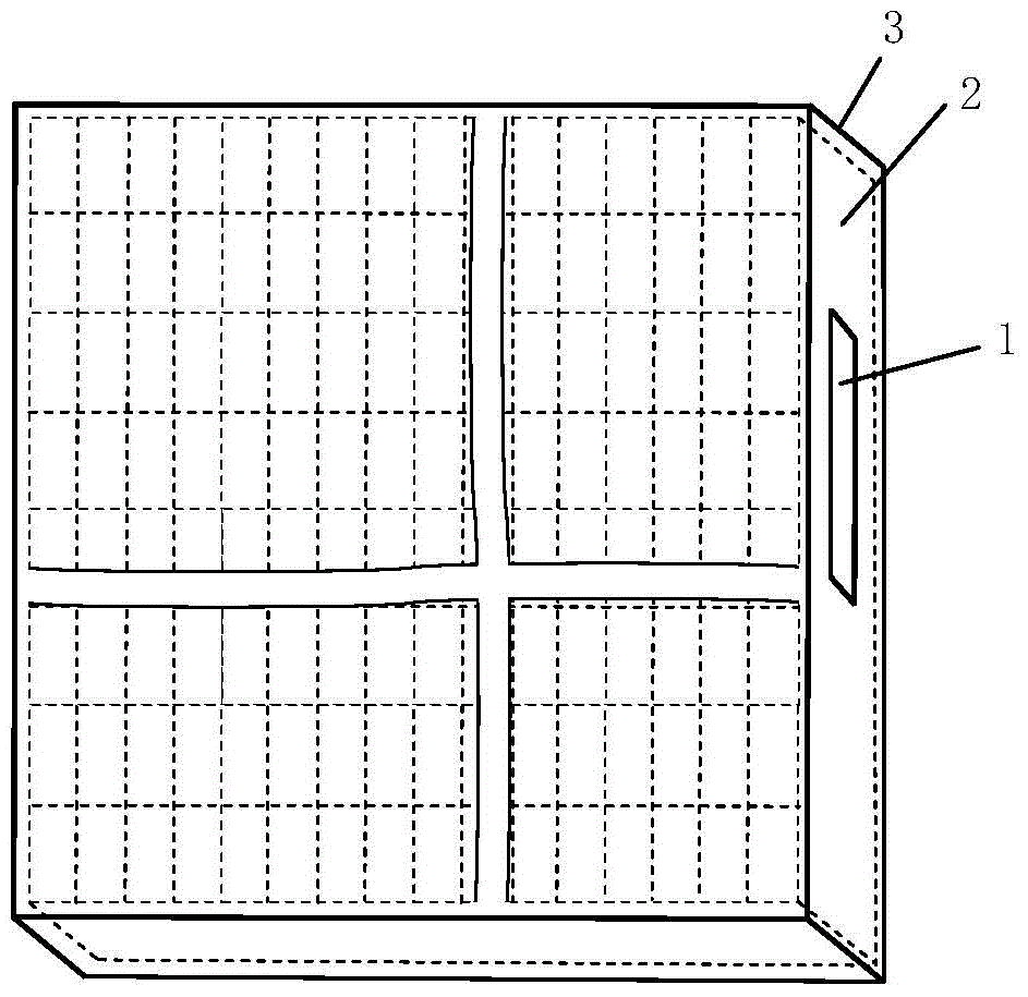
[0025] Such as figure 1 As shown, the infrared beam control chip based on the electronically controlled liquid crystal infrared diverging planar micro-cylindrical lens according to the embodiment of the present invention includes a chip housing 3 and an electronically controlled liquid crystal infrared diverging planar micro-cylindrical array 2 . The electronically controlled liquid crystal inf...


PUM

PropertyMeasurementUnit
porosityaaaaaaaaaa
porosityaaaaaaaaaa

Abstract

The invention discloses an infrared beam control chip based on an electric control liquid crystal infrared divergence planar micro-cylindrical-lens. The chip comprises an electric control liquid crystal infrared divergence planar micro-cylindrical-lens array, wherein the electric control liquid crystal infrared divergence planar micro-cylindrical-lens array comprises a liquid crystal material layer, a first liquid crystal initial orientation layer, a first electrical isolation layer, a graphical electrode layer, a first substrate, a first infrared antireflection film, a second liquid crystal initial orientation layer, a second electrical isolation layer, a common electrode layer, a second substrate and a second infrared antireflection film, the first liquid crystal initial orientation layer, the first electrical isolation layer, the graphical electrode layer, the first substrate and the first infrared antireflection film are sequentially arranged on the upper surface of the liquid crystal material layer, the second liquid crystal initial orientation layer, the second electrical isolation layer, the common electrode layer, the second substrate and the second infrared antireflection film are sequentially arranged on the lower surface of the liquid crystal material layer, the common electrode layer is composed of a homogeneous conducting film layer, and the graphical electrode layer is composed of a homogeneous conducting film layer on which rectangular hole pairs are distributed into an m*n element array. The chip can achieve electric control formation and modulation of a micro rectangular aperture array graphical optical field, can be easily matched and coupled with other infrared optical and photoelectric structures, electronic and mechanical devices and the like, and is good in environmental suitability.

Description

technical field [0001] The invention belongs to the technical field of precision measurement and control of infrared beams, and more specifically relates to an infrared divergent plane micro-cylindrical array based on electronically controlled liquid crystals, which is electrically controlled to construct adjustable arrayed micro-rectangular light holes arranged in an orderly manner A light control chip with a patterned light field. Background technique [0002] In recent years, the technology of columnar refraction or columnar diffraction light-diverging microlens arrays based on the surface relief profile to generate a specific form of light field constructed by the orderly arrangement of arrayed micro-rectangular light holes has been applied in many fields. . Typical infrared lithography sources such as arrayed micro-rectangular apertures in the large-scale integrated circuit lithography process, infrared direct-writing lithography sources for the fabrication of micro-re...

Claims


Application Information

Patent Timeline
Patent Type & Authority Patents(China)
IPC IPC(8): G02F1/1343G02F1/133G02F1/29G01J3/12
CPCG02F1/13306G02F1/134309G02F1/292
Inventor 张新宇雷宇佟庆罗俊桑红石谢长生
Owner HUAZHONG UNIV OF SCI & TECH
Why Eureka
Try Eureka