Self-adaptation voltage regulator circuit

A technology of self-adapting voltage and regulating circuit, applied in the direction of regulating electrical variables, control/regulating systems, electrical components, etc., can solve the problem that the tracking speed of operating frequency is easily limited by interface speed, performance limited nonlinearity and loop delay, Large output voltage ripple and other problems, to achieve the effects of good step response, reduced power loss, and fast voltage adjustment

Inactive Publication Date: 2015-01-21
UNIV OF ELECTRONICS SCI & TECH OF CHINA
View PDF3 Cites 35 Cited by
  • Summary
  • Abstract
  • Description
  • Claims
  • Application Information

AI Technical Summary

Problems solved by technology

[0003] The existing AVS technology currently has an AVS regulator based on pulse-skipping cycle modulation, which is characterized by a simple and effective structure, but at the same time has a limited load range and a large output voltage ripple problem; critical path replication (CPR) technology It is also used for delay quantization, but similar to the digital control adjustment period, its performance is limited by the non-linearity of output voltage quantization and loop delay; the combination of regulators and microprocessors through digital interfaces is also widely used, but its operating frequency tracking Speed ​​is easily limited by interface speed

Method used


Image

  • Self-adaptation voltage regulator circuit
  • Self-adaptation voltage regulator circuit
  • Self-adaptation voltage regulator circuit

Examples


Embodiment Construction

[0018] Below in conjunction with accompanying drawing and embodiment the present invention is described in detail

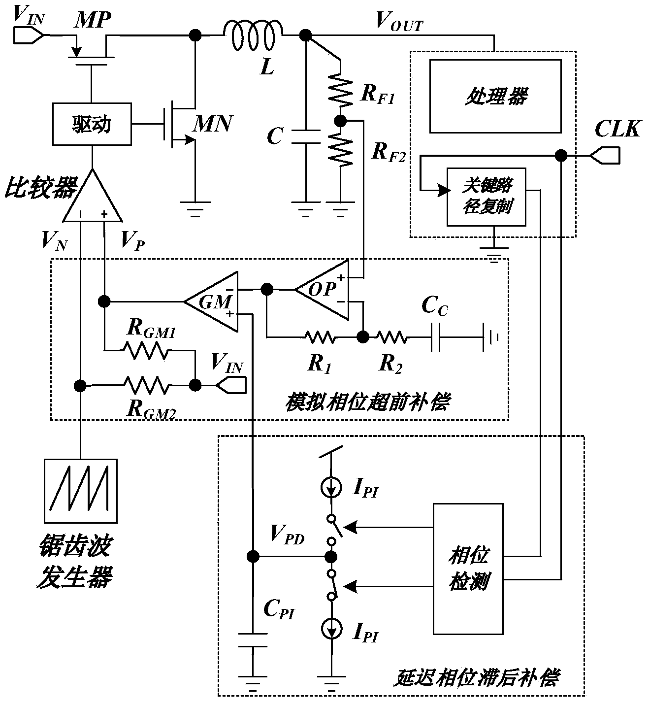
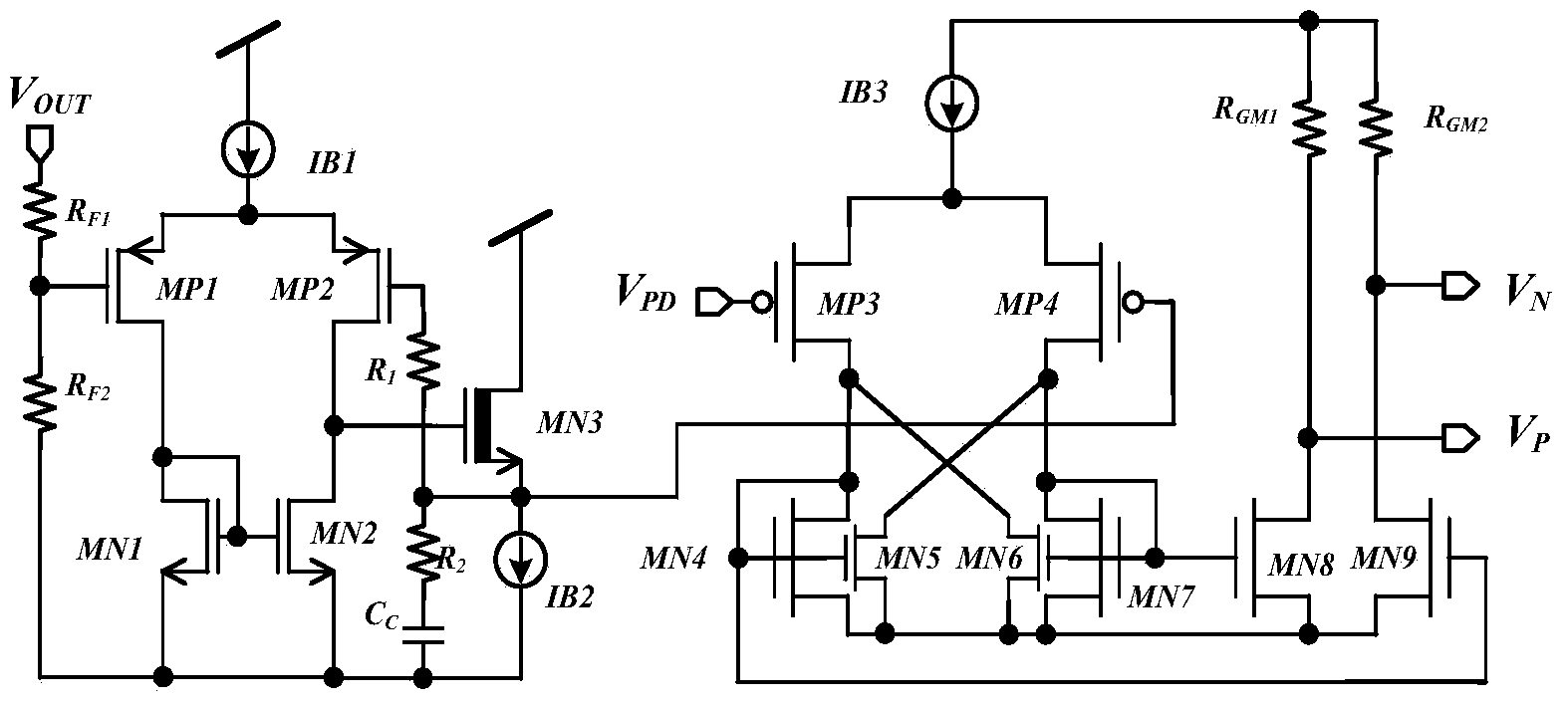
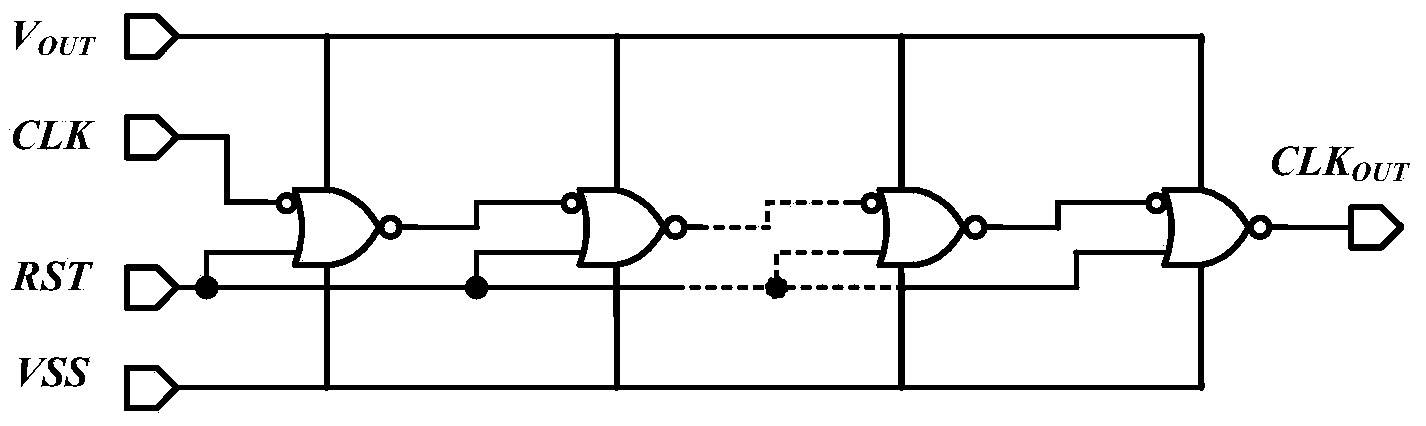
[0019] Such as figure 1 As shown, the present invention is an AVS circuit based on pseudo three-type compensation, including power transistors MP and MN, inductor L, capacitor C, first resistor RF1, second resistor RF2, analog phase lead compensation module, delay phase lag compensation Module, critical path replication module CPR, sawtooth wave generation module OSC, comparator Comp, power tube driver Driver. The output voltage Vout is divided by resistors Rf1 and Rf2. Operational amplifier OP, resistors R1 and R2, and capacitor Cc realize analog phase lead compensation. The operational transconductance amplifier GM load is R GM1 , which provides the loop gain for APD compensation. The delay of the critical path replication (CPR) is compared with the system clock CLK via phase detection (PD). Then, the delayed error signal is integrated by a charge pump. T...


PUM


Abstract

The invention belongs to the technical field of power sources and relates to a self-adaptation voltage regulator circuit. The self-adaptation voltage regulator circuit comprises a power tube MP, a power tube MN, an inductor L, a capacitor C, a first resistor RF1, a second resistor RF2, a simulation phase lead compensation module, a delay phase lag compensation module, a critical path duplication module, a sawtooth wave generating module, a comparator and a power tube driver. The output voltage Vout is partitioned by the first resistor RF1 and the second resistor RF2. Simulation phase lead compensation is achieved through an operational amplifier, the resistor R1, the resistor R2 and the capacitor C. A load of an operational transconductance amplifier GM is RGM1 and provides the loop gain of APD compensation. The delay of the duplication of the critical path is compared with a system clock CLK through phase detection. Then, delay error signals are integrated through a charge pump. The output voltage VPD of the charge pump is connected to the positive going input end of the operational transconductance amplifier GM. PWM waveforms can be obtained by comparing the sawtooth wave current generated by an oscillator OSC and the output current of the GM. By means of the self-adaptation voltage regulator circuit, the power loss of a digital circuit is greatly reduced.

Description

technical field [0001] The invention belongs to the technical field of power supplies and relates to an adaptive voltage regulation circuit. Background technique [0002] The power consumption of integrated circuits becomes more and more important with the development of the performance of portable electronic products and the trend of thinner and smaller. Adaptive Voltage Scaling (AVS) is an effective power management technology proposed in recent years. AVS adjusts the frequency according to a certain strategy by monitoring the hardware, and adjusts the voltage adaptively based on the working conditions of the load, which can further reduce the power consumption of the load by 30-70%. A great feature of this technology is that it can reduce system power consumption without affecting system functions and various indicators. Unlike look-up table-based dynamic voltage scaling (DVS) methods, adaptive voltage scaling (AVS) technology uses time-domain error clock periods and cr...

Claims


Application Information

Patent Timeline
Patent Type & Authority Applications(China)
IPC IPC(8): H02M3/156
CPCH02M3/1584H02M3/1586
Inventor 甄少伟杨东杰王骥曹灿华罗萍贺雅娟张波
Owner UNIV OF ELECTRONICS SCI & TECH OF CHINA
Why Eureka
Try Eureka