Low-altitude detection floating platform

A floating platform and low-altitude technology, which is applied in the field of low-altitude detection of floating platforms, can solve the problems of inability to obtain flight-related data, inability to identify ground conditions, inability to correct routes and positions of floating platforms, etc., to achieve comprehensive detection methods and safe use , Operational Effects

Active Publication Date: 2015-01-28
XIANGYANG HONGWEI AIRCRAFT
View PDF8 Cites 9 Cited by
  • Summary
  • Abstract
  • Description
  • Claims
  • Application Information

AI Technical Summary

Problems solved by technology

However, the floating platform cannot correct the route and position, nor can it identify the ground situation, and the ground cannot obtain real-time flight-related data

Method used


Image

  • Low-altitude detection floating platform
  • Low-altitude detection floating platform
  • Low-altitude detection floating platform

Examples


Embodiment 1

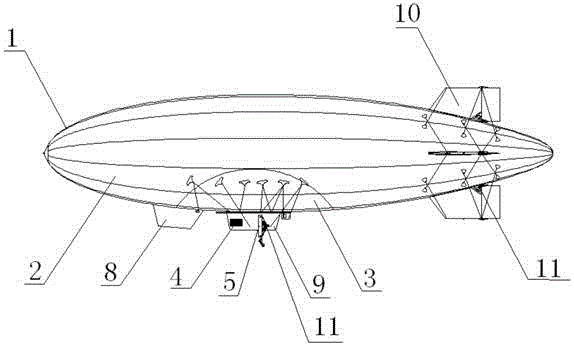
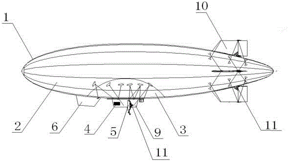
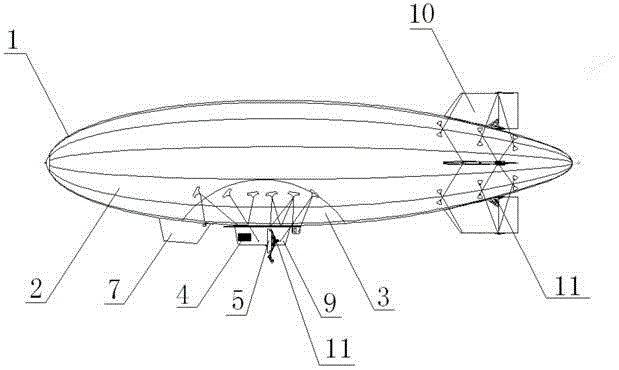
[0035] See Figure 1-5 The low-altitude detection floating platform of the present invention includes: a balloon 1 for providing buoyancy, which is composed of a main airbag 2 and a secondary airbag 3; a synthetic aperture radar 6 for ground detection; an optical system for ground monitoring Equipment 7; mission cabin 8 system, which is set on the underside of the balloon 1, including a first installation platform, the synthetic aperture radar 6 and optical equipment 7 are installed on the first installation platform; provides for floating platforms Powered power system 5; flight control system 4 for flight control; pod system 9, which is arranged on the lower side of the balloon 1, including a second installation platform, the flight control system 4 and the power system 5 are arranged On the second installation platform; and a tail system 10 for controlling the lift and steering of the floating platform; wherein the flight control system 4 is connected to the synthetic apertu...

Embodiment 2

[0045] See again Figure 1-5 , Which shows a schematic diagram of a low-altitude detection floating platform according to a preferred embodiment of the present invention. The low-altitude inspection floating platform may preferably include: a balloon 1 for providing buoyancy, which is composed of a main airbag 2 and a secondary airbag 3; a flight control system 4 for flight control; a power system 5 for providing power to the floating platform; Synthetic aperture radar 6 for ground detection; optical equipment (wide field of view equipment, thermal imaging equipment, infrared equipment) 7 for ground monitoring; mission cabin system 8 that provides installation platforms for synthetic aperture radar 6 and optical equipment 7; The flight control system 4 and the power system 5 provide the pod system 9 for installing the platform; the tail wing system 10 that controls the lifting and steering of the floating platform; and the digital steering gear 11 that controls the power system...


PUM


Abstract

A low-altitude detection floating platform comprises a balloon, synthetic aperture radar, optical equipment, a task cabin system, a power system, a flight control system, a pod system and a tail fin system; the balloon used for providing floating force comprises a main balloon and an auxiliary balloon; the synthetic aperture radar is used for ground detection; the optical equipment is used for ground monitoring; the task cabin system is disposed at the bottom of the balloon and comprises a first mounting platform; the synthetic aperture radar and the optical equipment are mounted on the first mounting platform; the power system provides power for the floating platform; the flight control system is used for flight control; the pod system is disposed at the bottom of the balloon and comprises a second mounting platform; the flight control system and the power system are disposed on the second mounting platform; the tail fin system is used for controlling ascent, descent and turning of the floating platform; the flight control system is connected with the synthetic aperture radar, the optical equipment, the power system and the tail fin system. The low-altitude detection floating platform has the advantages that means of detection are more comprehensive, operating is more comprehensive, using is safer, and detecting positions and paths can be corrected in real time.

Description

Technical field [0001] The invention relates to the field of floating platforms. Specifically, it relates to a low-altitude detection floating platform. Background technique [0002] The applicant’s own invention patent with publication number CN102874402A discloses a closed pressurized hot air floating platform, which includes a lift system, a hanging rope, a pod, a mooring cable, a guide plate, a hydraulic winch, and an anchored car And the control system, the lift system is connected with the pod through the hanging rope, the upper end of the mooring rope is connected with the lower end of the hanging rope, the lower end of the mooring rope is installed on the guide plate, and the guide plate and the hydraulic winch are fixed to the anchor in turn On the vehicle; the lift system includes a capsule, a one-way pressure relief valve, a booster fan, a heater and a booster component. The floating platform has the advantages of high rigidity of the capsule body, strong wind resist...

Claims


Application Information

Patent Timeline
Patent Type & Authority Applications(China)
IPC IPC(8): B64B1/58B64B1/22B64D47/00
Inventor 陈勇薛富利贺应平郭海军李琦田入东马启明余刚
Owner XIANGYANG HONGWEI AIRCRAFT
Why Eureka
Try Eureka