
Substrate integrated waveguide band-pass filter applied onto WLAN (wireless local area network) system

A substrate-integrated waveguide and bandpass filter technology, applied in the field of wireless communication, can solve problems such as difficult design and processing, complex structure, etc., and achieve the effect of overcoming large loss, high selectivity, and simple structure

Inactive Publication Date: 2015-01-28
SOUTH CHINA UNIV OF TECH
View PDF4 Cites 15 Cited by
  • Summary
  • Abstract
  • Description
  • Claims
  • Application Information

AI Technical Summary

Problems solved by technology

Simulation results such as Figure 5c As shown, the relative bandwidth is close to 65%, and the loss is small, but this structure is more complicated and not easy to design and process

Method used


Image

  • Substrate integrated waveguide band-pass filter applied onto WLAN (wireless local area network) system
  • Substrate integrated waveguide band-pass filter applied onto WLAN (wireless local area network) system
  • Substrate integrated waveguide band-pass filter applied onto WLAN (wireless local area network) system

Examples


Embodiment 1

[0048] This embodiment designs a basic substrate integrated waveguide bandpass filter, such as Image 6 As shown, the filter includes a substrate-integrated waveguide (SIW), and the substrate-integrated waveguide includes a dielectric substrate 1 and two layers of metal patches arranged on the front and back of the dielectric substrate 1 (the metal patches on the front are marked with numbers 2. The metal patch on the reverse side is not shown in the figure, and the embodiment 2 and 3 are the same) and several metal through holes 3, and the several metal through holes 3 pass through the metal patch 2 on the front side of the dielectric substrate 1, the dielectric The metal patch on the back side of the substrate 1 and the dielectric substrate 1, the metal through holes 3 surround the metal patch 2 on the front side of the dielectric substrate 1 to form two rectangular cavities (upper and lower rectangular cavities) of the same size. body marked number 4, lower rectangular cavi...

Embodiment 2

[0053] This embodiment also designs a basic substrate integrated waveguide bandpass filter, such as Figure 11 As shown, the difference between the structure of this filter and Embodiment 1 is that: the left side of the upper rectangular cavity 4 is provided with a first feeder 6, and the left side of the lower rectangular cavity 5 is provided with a second feeder 7, also That is to say, the first feeder 6 and the second feeder 7 are located on the same side.

[0054] like Figure 12 As shown, the S parameters of the above structure (S 11 parameter refers to the return loss of the input port, S 21 The parameter refers to the forward transmission coefficient from the input port to the output port) In the response, it can also be seen that the passband center frequency of the filter is 4.3GHz, and the passband is formed by using the TE of the substrate integrated waveguide 101 mode, but compared with the simulation curve of the structure of embodiment 1, a pair of transmissio...

Embodiment 3

[0057] In Example 2 of Figure 13 On the basis of the structure, make improvements to the feeder part, such as Figure 15 As shown, the first branch 10 is loaded on the first feeder 6, the second branch 11 is loaded on the second feeder 7, the first branch 10 extends downward, the second branch 11 extends upward, and the first branch 11 The node 10 and the second branch 11 do not overlap with each other, and the source-load coupling is used to increase the transmission zero point and improve the selectivity of the filter, which from Figure 16 (The dotted line represents the simulation result of unloaded branches, and the solid line represents the simulation results of loaded branches). It can be seen that after loading branches, S 21 The parameter adds a pair of transmission zeros near 5.3GHz, which reduces the out-of-band attenuation from about 20dB to below 35dB, improving the filter squareness, that is, improving the selectivity of the filter.

[0058] To verify the abov...


PUM


Abstract

The invention discloses a substrate integrated waveguide band-pass filter applied onto a WLAN (wireless local area network) system. The substrate integrated waveguide band-pass filter applied onto the WLAN system comprises a substrate integrated waveguide, wherein the substrate integrated waveguide comprises a medium substrate, two layers of metal patches arranged on the obverse side and the reverse side of the medium substrate and a plurality of metal holes, the plurality of the metal holes sequentially run through the metal patch arranged on the obverse side of the medium substrate, the medium substrate and the metal patch arranged on the reverse side of the medium substrate, the plurality of the metal holes surround the metal patch arranged on the obverse side of the medium substrate into an upper rectangular cavity and a lower rectangular cavity which are of the same size, a first via hole is formed in the center of the upper rectangular cavity, a second via hole is formed in the center of the lower rectangular cavity, and the first via hole and the second via hole sequentially run through the metal patch arranged on the obverse side of the medium substrate, the medium substrate and the metal patch arranged on the reverse side of the medium substrate. Performance of the substrate integrated waveguide band-pass filter applied onto the WLAN system filter is improved by forming the via holes, and therefore the substrate integrated waveguide band-pass filter applied onto the WLAN system has the advantages of being simple in structure and high in selectivity, and can meet requirements for wireless communications of the WLAN system.

Description

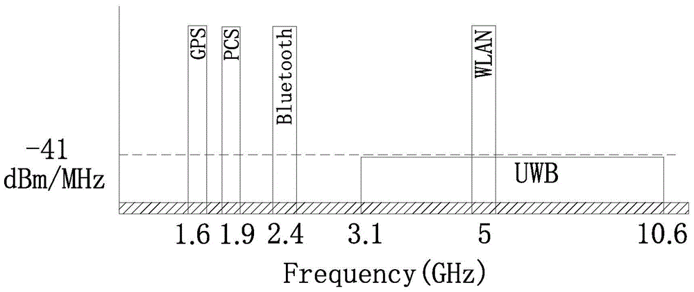
technical field [0001] The invention relates to a broadband substrate-integrated waveguide filter, in particular to a substrate-integrated waveguide band-pass filter applied to a WLAN system, belonging to the field of wireless communication. Background technique [0002] With the rapid development of wireless communication technology, especially 4G communication technology represented by LTE, on the one hand, spectrum resources are becoming more and more scarce. On the other hand, as an important part of the wireless communication field, the demand for bandpass filters is also The development of communication technology is increasing day by day. like figure 1 As shown in , as an important part of wireless communication, WLAN system occupies an important position in real life, so for band-pass filters, the design of band-pass filters applied in WLAN frequency band has a wide range of practical applications and urgent practical need. [0003] Substrate Integrated Waveguide ...

Claims


Application Information

Patent Timeline
IPC IPC(8): H01P1/20
Inventor 王世伟汪凯郭在成郑丽昇褚庆昕
Owner SOUTH CHINA UNIV OF TECH
Learn More