
Fluidized bed sludge incineration system and treatment method

A sludge incineration and fluidized bed technology, which is applied in the combustion method, incinerator, combustion type, etc., can solve the problems of secondary pollution, reduced sludge moisture content, non-environmental protection, etc., and achieves low cost and good separation effect. Effect

Active Publication Date: 2016-08-10
成都首创环境工程有限公司
View PDF8 Cites 0 Cited by
  • Summary
  • Abstract
  • Description
  • Claims
  • Application Information

AI Technical Summary

Problems solved by technology

The traditional method of sludge incineration is: first dehydrate and concentrate the sludge with a moisture content of more than 99%, and then make the moisture content of the sludge below 80%. At this time, the dehydration and concentration method cannot further reduce the moisture content of the sludge. At this time, it is necessary to use a drying machine to evaporate the moisture in the sludge by means of electric heating or natural gas heating, so that the moisture content of the sludge can be further reduced to below 60%. At this time, the sludge can be burned by high temperature heating The substances in the sludge are burned, and the flue gas to be treated is directly or indirectly treated and discharged. Therefore, in the traditional sludge incineration technology, an independent flue gas treatment equipment is required, which will undoubtedly increase equipment costs and maintenance costs. , sometimes in order to reduce costs, the owner directly discharges the generated flue gas directly, causing secondary pollution, which does not meet the country's environmental protection needs

Method used


Image

  • Fluidized bed sludge incineration system and treatment method

Examples


Embodiment 1

[0028] Such as figure 1 as shown,

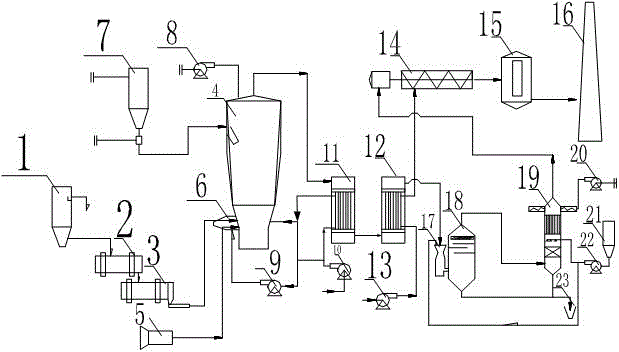
[0029]The fluidized bed sludge incineration system includes a sludge incineration device, a two-stage heat exchange device, a washing and dust removal device, and a secondary combustion device. The sludge incineration device includes a fluidized bed incinerator 4, and the two-stage heat exchange device includes a primary exchange Heater 11 and secondary heat exchanger, the heat passage of primary heat exchanger 11 communicates with the top gas outlet of fluidized bed incinerator 4, the heat passage of primary heat exchanger 11 is also connected with the heat of secondary heat exchanger The channels are connected in series, the heat channel of the secondary heat exchanger is connected with the washing and dust removal device, and the washing and dust removal device is also connected with the secondary combustion device, the cold channel of the primary heat exchanger 11 is connected with the fluidized bed incinerator 4, and the secondary The ...

Embodiment 2

[0040] The processing method based on the above-mentioned fluidized bed sludge incineration system comprises the following steps:

[0041] A. Sludge drying step: the sludge in the sludge tank is dried after passing through a sludge dehydrator and a sludge dryer;

[0042] B, sludge incineration step: send the dried sludge in the previous step into the fluidized bed incinerator 4 for combustion;

[0043] C. Heat exchange step: input the waste gas particle mixture output from the top outlet of the fluidized bed incinerator 4 into the heat channel of the primary heat exchanger 11, and pass the heat through the heat channel and the cold channel of the primary heat exchanger 11 Exchange, absorb the heat of the waste gas particle mixture, and the absorbed heat flows back into the fluidized bed incinerator 4, and the cooled waste gas particle mixture flows into the heat channel of the next secondary heat exchanger, and passes through the heat channel of the secondary heat exchanger. ...


PUM


Abstract

The invention discloses a fluidized bed sludge incineration system and a processing method. The fluidized bed sludge incineration system comprises a sludge incineration device, a two-stage heat exchange device, a cleaning dust collection device and a secondary combustion device, wherein the sludge incineration device comprises a fluidized bed incinerator; the two-stage heat exchange device comprises a first-stage heat exchanger and a second-stage heat exchanger; a heat channel of the first-stage heat exchanger is communicated with a top air outlet of the fluidized bed incinerator; the heat channel of the first-stage heat exchanger is communicated with a heat channel of the second-stage heat exchanger; the heat channel of the second-stage heat exchanger is connected with the cleaning dust collection device; the cleaning dust collection device is also connected with the secondary combustion device; a cold energy channel of the first-stage heat exchanger is communicated with the fluidized bed incinerator; a cold energy channel of the second-stage heat exchanger is communicated with the secondary combustion device. Multi-stage heat exchange is arranged, so that the heat reutilization is achieved, and meanwhile, a heat recycling heating system is utilized, exhaust gas is subjected to exhaust gas solidifying and absorbing, and then the secondary combustion is performed, so that the cost and the size of the secondary combustion device are both minimized.

Description

technical field [0001] The invention relates to a sorting treatment device and a treatment method for garbage, and belongs to the technical field of environmental protection sludge treatment. Background technique [0002] At present, the discharge of urban industrial wastewater and domestic sewage is increasing day by day, the amount of sewage treatment is increasing, and the sludge output of sewage treatment plants is also increasing sharply. While using physical, chemical and biological methods to treat sewage, a large amount of excess sludge will be produced. Among them, the sludge with high organic content must be treated and disposed of in time, otherwise it will cause secondary pollution. The final solution of sludge is mainly used: landfill , agricultural, drying and incineration. Due to industrial development, the content of heavy metals in sludge has exceeded the standard in most cases and cannot be directly used for agriculture. At the same time, due to the contin...

Claims


Application Information

Patent Timeline
Patent Type & Authority Patents(China)
IPC IPC(8): F23G7/00F23J15/00F23L15/00
CPCF23G7/001F23G2203/50F23J15/006F23L15/00Y02E20/34
Inventor 胡登容杨子容郑传勇陈刚
Owner 成都首创环境工程有限公司
Learn More