Full-automatic laser carving machine for straps

A laser cutting and engraving machine technology, used in laser welding equipment, welding equipment, metal processing and other directions, can solve the problems of engraving pattern deformation, take-off speed acceleration lag, beam thickening and other problems, to reduce specifications and flatness requirements, Improve take-off speed and acceleration, avoid the effect of black and yellow

Active Publication Date:
View PDF8 Cites 8 Cited by
  • Summary
  • Abstract
  • Description
  • Claims
  • Application Information

AI Technical Summary

Problems solved by technology

[0003] At present, laser engraving uses a focusing mirror to converge a laser beam with a diameter of about 6 mm to a focus point with a diameter of about 0.1 mm, and then uses the focus point to engrave the material. The laser head and working platform of a traditional engraving machine (honeycomb plate ) must be kept consistent. When processing strip-shaped materials, the material needs to be placed flat on the fixed position of the honeycomb panel to ensure the engraving accuracy. If the material is not flat, the focus will occur Larger changes, the material deviates from the focus point, the beam becomes thicker, and the penetrating power is poor, resulting in deformation of the engraving pattern or engraving not piercing through, which affects the engraving effect; then, the X-axis and Y-axis command the laser head to move, and the laser head moves on the strip material. Engraving or cutting out the pattern; after the engraving is completed, the machine is in standby mode, and the engraved products are manually put away, and then the waste carved on the honeycomb panel is cleaned. If the operation is repeated, if the engraving pattern is relatively simple, the standby time of the machine is often longer than the working time It is also long, which makes the machine unable to engrave and cut continuously for a long time, resulting in low production efficiency. In order to ensure a certain production efficiency, each double laser head engraving machine needs 1-2 workers to operate, which wastes manpower to a certain extent
[0004] In the production process, due to the high-density energy characteristics of the laser, when laser cutting upper materials, especially light-colored materials (such as white beige, etc.), or special materials (such as mirror materials, etc.), the bottom surface of the material is easy to appear The phenomenon of yellowing and blackening [During engraving, due to the high temperature during engraving, it is easy to generate smoke and dust. The bottom surface of the material placed flat on the honeycomb board and the place where the honeycomb board touches, the smoke cannot be dispersed in time, and it is affected by the smoke. It will cause the bottom surface of the material to turn yellow and black, which will affect the yield rate of the product]
In order to prevent this phenomenon, during production and processing, it is necessary to carry out certain protection treatment on the bottom surface of the material. The usual methods are: 1. Paste the protective film, it must be flat and tight, without air bubbles, and the processing is completed. Then remove the protective film, but this undoubtedly increases the processing difficulty and cost, the processing procedure becomes cumbersome, and increases the production time and production cost; 2. Apply cleaning agent to some shoe uppers, wash them off after carving, this method is applicable For some materials, the scope of implementation is relatively limited; 3. To adjust the laser processing parameters, the method of multiple times of small firepower is adopted, but the processing effect of the material is easily affected by the material displacement or processing error during the multiple processing process, which increases the Processing procedures, limiting production efficiency
[0005] In addition, in actual production, the existing engraving machine needs to drive the entire X-axis to move together when the Y-axis moves. The device makes the Y-axis move with a large load, causing the machine's take-off speed (the reaction speed of the engraving head to move from rest) and acceleration (the speed of the engraving head to move from the beginning to the speed set by the user) to lag behind. Due to the influence of its own weight, it is easy to shake during processing, resulting in jagged patterns on the engraved patterns, which affects the processing effect

Method used


Image

  • Full-automatic laser carving machine for straps
  • Full-automatic laser carving machine for straps
  • Full-automatic laser carving machine for straps

Examples


Embodiment Construction

[0021] The present invention will be further described below in conjunction with accompanying drawing of description:

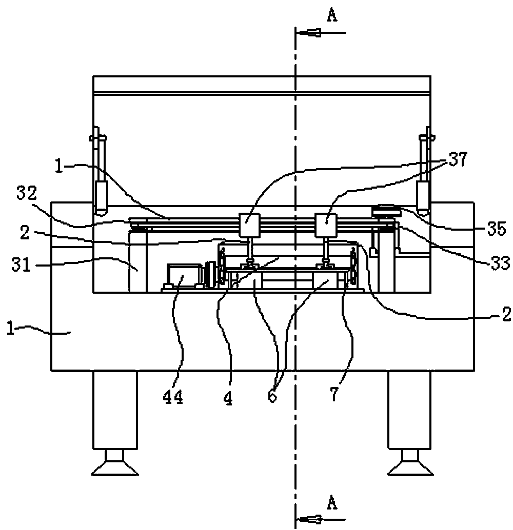
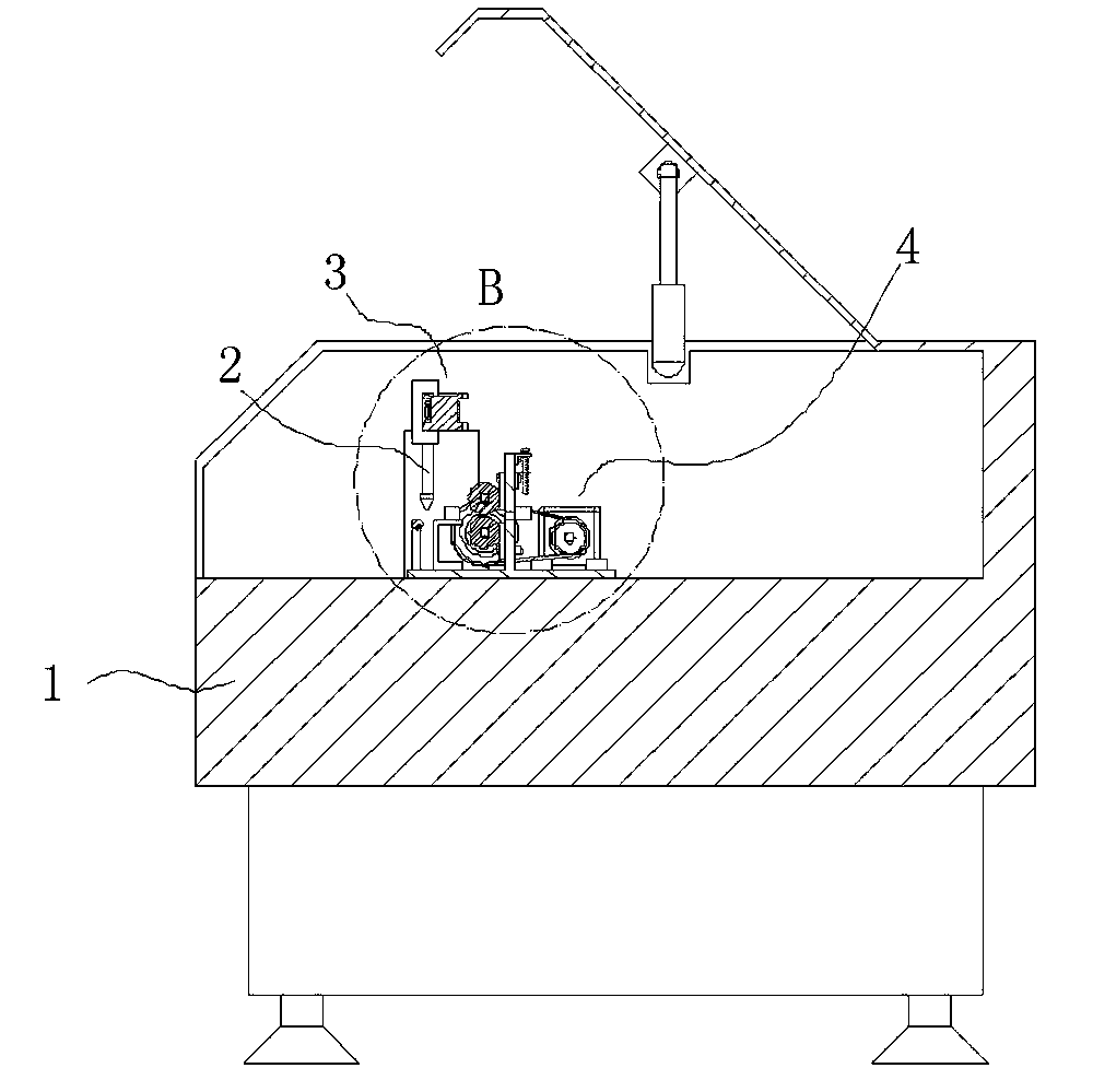
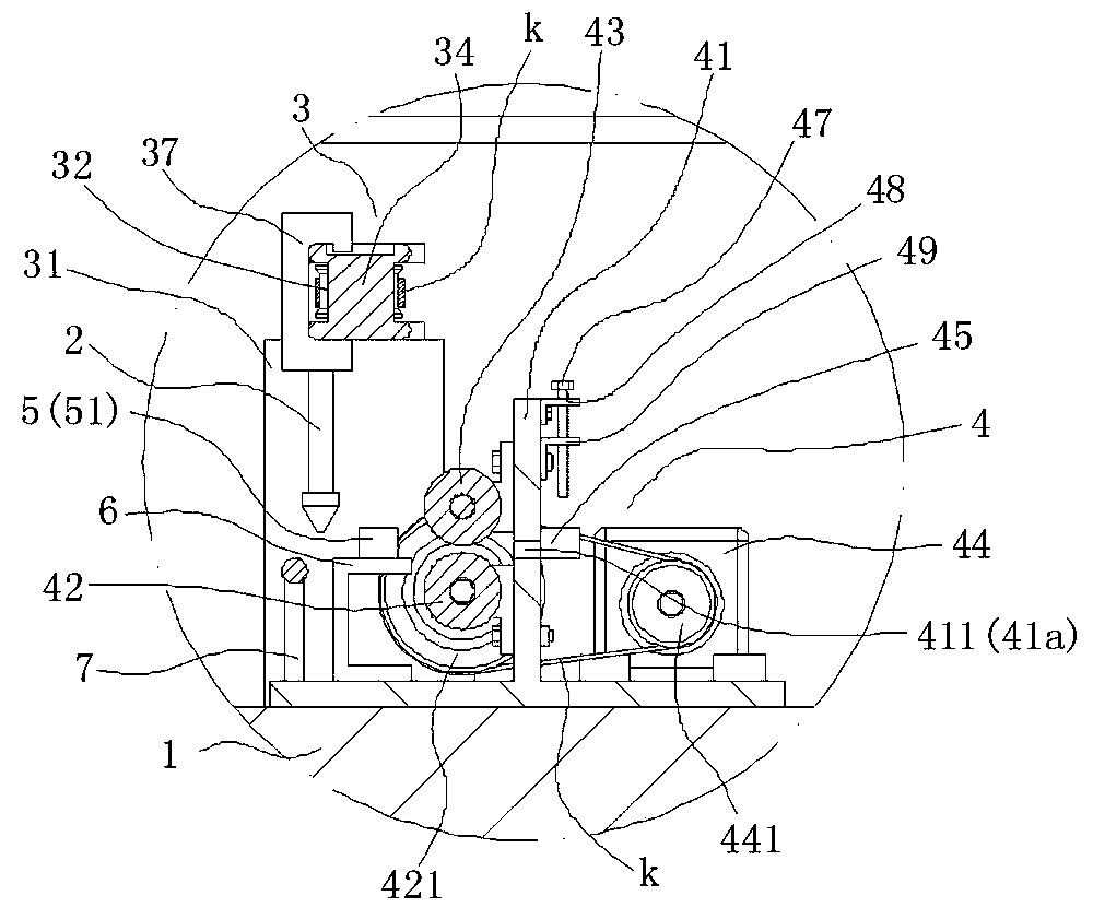
[0022] Such as Figure 1-5 As shown, the present invention relates to a fully automatic strip laser cutting engraving machine, which includes: a body 1, an engraving head 2 for engraving and cutting, an X-axis 3 that enables the engraving head 2 to feed horizontally, and allows the material to be fed vertically The feeding mechanism 4.

[0023] Such as Figure 1-5 As shown, the feeding mechanism 4 is arranged on the fuselage 1, and the feeding mechanism 4 is composed of a base plate 46 connected to the fuselage 1, a material guide plate 41 vertically arranged on the base plate 46, and an active material guide plate 41 vertically arranged side by side at the front end of the material guide plate 41. The feeding shaft 42 is composed of a driven feeding shaft 43 and a driving part 44 which is transmission-connected with the driving feeding shaft 42 .

[0024]...


PUM


Abstract

The invention discloses a full-automatic laser carving machine for straps. The full-automatic laser carving machine for the straps comprises a machine body, a carving head, an X shaft and a feeding mechanism. The feeding mechanism is arranged on the machine body and comprises a bottom plate, a guide plate, a driving feeding shaft, a driven feeding shaft and a driving portion, wherein the guide plate is perpendicularly arranged on the bottom plate which is connected with the machine body, the driving feeding shaft and the driven feeding shaft are abreast mounted at the front end of the guide plate vertically, and the driving portion is in transmission connection with the driving feeding shaft. The guide plate is provided with a feeding port, the back of the guide plate is provided with a plurality of conveniently-adjustable guide limiting positions at the feeding port, and a guide port is formed between each two guide limiting positions. The driving feeding shaft is provided with a limiting outlet in the feeding direction, a supporting bar for auxiliary supporting of materials is arranged at the front end of the limiting outlet, and the carving head is arranged above a gap position between the limiting outlet and the supporting bar. The full-automatic laser carving machine for the straps has the advantages of simplicity in operation, high in jumping speed and acceleration, improvement of machining precision, guarantee of product yield, reduction of consumption, improvement of production efficiency and saving of manpower and material resources.

Description

technical field [0001] The invention relates to the technical field of strip material engraving processing production equipment, in particular to a fully automatic strip laser cutting and engraving machine. Background technique [0002] The laser engraving machine can improve the engraving efficiency, make the surface of the engraved place smooth and round, rapidly reduce the temperature of the engraved non-metallic material, and reduce the deformation and internal stress of the engraved object; it can be widely used for various non-metallic materials Materials for finely carved areas. The advantage of laser processing is that it can quickly engrave and hollow out various patterns on the surface of various shoe upper materials. Since laser processing is a non-contact processing method, it will not cause any external deformation to the upper. It also has many advantages such as high engraving precision, hollow out without burr, and can process any shape. [0003] At present...

Claims


Application Information

Patent Timeline
Patent Type & Authority Applications(China)
IPC IPC(8): B23K26/362B23K26/70B23K26/08
CPCB23K26/0869B23K2101/16
Inventor 林映勉
Why Eureka
Try Eureka