
Electric control liquid crystal laser shaping chip based on wave front adjustment

A laser shaping and liquid crystal technology, applied in optics, nonlinear optics, instruments, etc., can solve the problems of long state transition time, difficult to integrate into space and drive control, large volume and mass, etc. The effect of flexible control mode and high control precision

Active Publication Date: 2015-02-11
HUAZHONG UNIV OF SCI & TECH
View PDF6 Cites 4 Cited by
  • Summary
  • Abstract
  • Description
  • Claims
  • Application Information

AI Technical Summary

Problems solved by technology

At present, the construction or modulation of laser beams with specific shapes and energy states is generally carried out through optical systems composed of refractive and diffractive lenses with fixed contours. The obvious defects include: (1) large volume and mass, cost High, the optical structure is relatively complex, and it is difficult to miniaturize; (2) The beam modification or modulation operation is usually based on the mechanical movement between the lenses. Slow, long state transition time, unable to perform arbitrary optical state cut-in or jump due to the continuity of mechanical motion
MEMS spatial light modulators that have been widely used mainly based on reflection work are difficult to integrate into the optical path or structure with limited space and drive control due to their working mechanism

Method used


Image

  • Electric control liquid crystal laser shaping chip based on wave front adjustment
  • Electric control liquid crystal laser shaping chip based on wave front adjustment
  • Electric control liquid crystal laser shaping chip based on wave front adjustment

Examples


Embodiment Construction

[0020] In order to make the object, technical solution and advantages of the present invention clearer, the present invention will be further described in detail below in conjunction with the accompanying drawings and embodiments. It should be understood that the specific embodiments described here are only used to explain the present invention, not to limit the present invention. In addition, the technical features involved in the various embodiments of the present invention described below can be combined with each other as long as they do not constitute a conflict with each other.

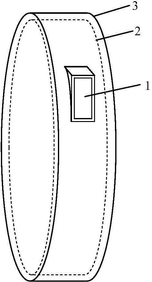
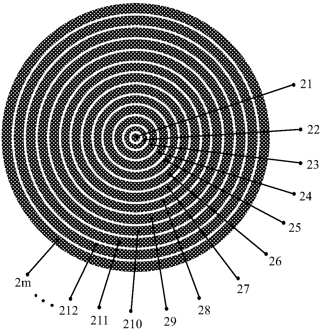
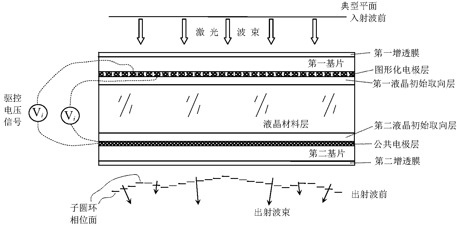
[0021] Such as figure 1 As shown, the electronically controlled liquid crystal laser shaping chip based on wavefront adjustment according to the embodiment of the present invention includes a chip housing 3 and a cylindrical liquid crystal phase modulation structure 2 . The liquid crystal phase modulation structure 2 is packaged in the chip case 3 and fixedly connected with the chip case 3 , an...


PUM


Abstract

The invention discloses an electric control liquid crystal laser shaping chip based on wave front adjustment. The chip comprises a cylindrical liquid crystal phase modification framework, wherein the liquid crystal phase modification framework comprises a liquid crystal material layer, a first liquid crystal initial alignment layer, an imaging electrode layer, a first substrate and a first antireflection film which are arranged on the upper surface of the liquid crystal material layer in sequence, and a second liquid crystal initial alignment layer, a common electrode layer, a second substrate and a second antireflection film which are arranged on the lower surface of the liquid crystal material layer in sequence; the common electrode layer is composed of a homogeneous conducting film; the imaging electrode layer is composed of a circular conducting film and at least one circular ring-shaped conducting film concentrically arranged on the periphery of the circular conducting film, and the circle center of the circular conducting film coincides with the axis of the liquid crystal phase modification framework; when a plurality of circular ring-shaped conducting films are arranged, the radial widths of all circular ring-shaped conducting films are equal, and the radial space of adjacent conducting films is equal. The chip is large in laser beam shaping variation range, good in adaptability and small in size and mass, and is easily coupled with other optical and optoelectronic mechanical structures.

Description

technical field [0001] The invention belongs to the technical field of laser beam shaping and control, and more specifically relates to an electronically controlled liquid crystal laser shaping chip based on wavefront adjustment. Background technique [0002] So far, laser technology with specific beam shape and energy state has been widely used in many fields, such as laser communication, laser pointer, laser processing, laser exposure, laser ablation and cleaning, laser engraving and shape modification, laser Cosmetology, laser physiotherapy, laser scanning, laser irradiation, laser printing, laser cooling, laser display, laser propulsion, laser ignition, laser atomic manipulation, laser imaging, laser lighting, laser interconnection, laser interference and laser attack, etc. With the continuous and rapid development of laser technology and the continuous expansion and extension of application fields, laser beams with more complex shapes and energy states are constructed. ...

Claims


Application Information

Patent Timeline
IPC IPC(8): G02F1/1343G02F1/1333G02F1/133
CPCG02F1/13306G02F1/134309
Inventor 张新宇雷宇佟庆罗俊桑红石谢长生
Owner HUAZHONG UNIV OF SCI & TECH
Learn More