Coupling inductive type interleaving parallel Boost soft switch circuit

A coupled inductor and soft switching technology, which is applied in the direction of high-efficiency power electronic conversion, electrical components, and conversion equipment without intermediate conversion to AC, can solve the problems affecting the application of soft switching converters and the increase in converter volume, and achieve improved circuit performance. Effects of conversion efficiency, reduction of switching loss, and avoidance of reduction in power density

Active Publication Date: 2015-02-11
氢荣(上海)新能源科技有限公司
View PDF2 Cites 4 Cited by
  • Summary
  • Abstract
  • Description
  • Claims
  • Application Information

AI Technical Summary

Problems solved by technology

However, the additional auxiliary network added to achieve the soft switching effect often increases the overall volume of the conv

Method used


Image

  • Coupling inductive type interleaving parallel Boost soft switch circuit
  • Coupling inductive type interleaving parallel Boost soft switch circuit
  • Coupling inductive type interleaving parallel Boost soft switch circuit

Examples


Embodiment

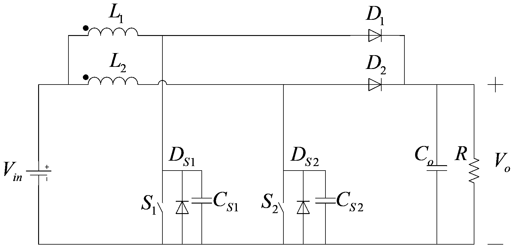
[0020] See attached figure 1 , the circuit of the present invention uses coupled inductors to replace common boost inductors in traditional interleaved parallel Boost topology. The coupled inductance interleaved parallel Boost soft switching circuit includes two boost inductors L 1 , L 2 , two freewheeling diodes D 1 、D 2 , two power switches S 1 , S 2 , two auxiliary diodes D S1 、D S2 , two auxiliary capacitors C S1 、C S2 . The first freewheeling diode D 1 The common anode is connected to the first power switch tube S 1 the drain of the second freewheeling diode D 2 The common anode is connected to the second power switch tube S 2 Drain of the first auxiliary diode D S1 , the second auxiliary diode D S2 respectively connected in parallel with two power switch tubes S 1 , S 2 Both ends; the first auxiliary capacitor C S1 , the second auxiliary capacitor C S2 respectively connected in parallel with two power switch tubes S 1 , S 2 Both ends; input DC power ...


PUM


Abstract

The invention relates to a coupling inductive type interleaving parallel Boost soft switch circuit. The circuit comprises a boost inductor, and the boost inductor employs two mutually coupled inductors to replace a common boost circuit in a conventional interleaving parallel Boost topology. Compared to the prior art, through switch tubes, zero-voltage switching (a duty ratio is greater than 0.5) and zero-current switching (the duty ratio is smaller than 0.5) are realized, such that switch loss is reduced, and circuit total efficiency is improved; and a soft switch effect is realized by use of a coupling inductive leakage inductor, no additional auxiliary elements are added, and no influences are caused to the power density of a converter.

Description

technical field [0001] The invention relates to a soft switch circuit, in particular to a coupled inductance type interleaved parallel Boost soft switch circuit for high-power non-isolated DC / DC applications. Background technique [0002] In many fields such as aerospace, electric vehicles, and photovoltaic power generation, high-power DC / DC converters are essential components. How to effectively select and adjust its parameters, increase power density, improve conversion efficiency, and improve electromagnetic interference (EMI) is not only related to the normal operation of the converter itself, but also related to the optimization of the overall performance of the system and the improvement of energy utilization efficiency And the stable and reliable operation of the control part. [0003] Increasing the switching frequency is an important means to increase the power density of the DC / DC converter. However, due to the non-ideal characteristics of power devices, the high...

Claims


Application Information

Patent Timeline
IPC IPC(8): H02M3/10
CPCH02M3/155Y02B70/10
Inventor 韦莉刘帅张逸成杨晓盛詹地夫姚勇涛沈玉琢张佳佳顾帅叶尚斌
Owner 氢荣(上海)新能源科技有限公司
Why Eureka
Try Eureka