Pipeline system capable of utilizing biogas slurry efficiently

A pipeline system and biogas slurry technology, which is applied in agriculture and the environment, can solve the problems of low filtration efficiency and difficulty in biogas slurry utilization, and achieve the effects of improving filtration efficiency, preventing and controlling various diseases and insect pests, and having broad application prospects

Active Publication Date: 2015-02-18
JIANGSU ACAD OF AGRI SCI
View PDF6 Cites 6 Cited by
  • Summary
  • Abstract
  • Description
  • Claims
  • Application Information

AI Technical Summary

Problems solved by technology

The pipeline system and method combine the filter box and the micro-irrigation pipeline to effectively prevent the clogging of the biogas slurry, and solve the problem of difficult utilization of the biogas slurry due to low filtration efficiency and various forms of suspended solids in the biogas slurry, and have broad application prospects

Method used


Image

  • Pipeline system capable of utilizing biogas slurry efficiently

Examples


Embodiment 1

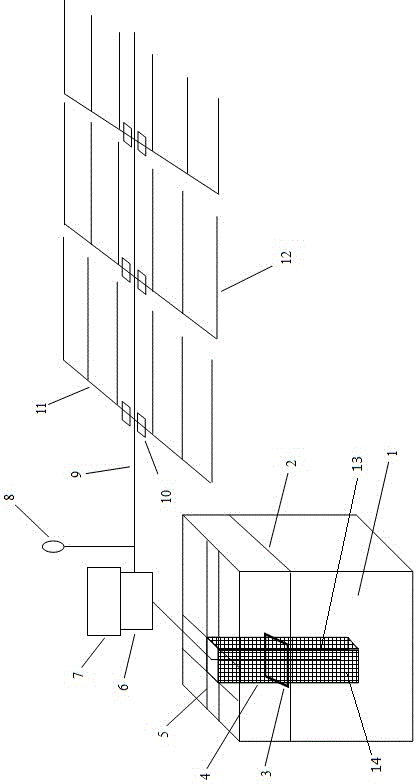
[0022] Example 1: Corn Biogas Slurry Pipeline System and Utilization

[0023] Such as figure 1 , Pipeline utilization of biogas slurry in corn fields. The corn field is rectangular, with an area of ​​45*115m. Biogas slurry pool 1 is located in the middle of one side of the field, in a square shape, with a side length of 5.3m, a pool depth of 2.4m, and a volume of biogas slurry of 60m 3 about. The surroundings of the filter box 4 are fixed with brackets 5 and placed in the middle of the biogas slurry tank 1 with an area of ​​1m 2 , 2m deep, consisting of a steel frame 13 and a steel wire mesh 14, the steel wire mesh 14 is wrapped on the periphery of the steel frame on three sides, with the opening upward; the mesh of the steel mesh is 60 mesh. The anti-blocking ring 3 is set on the outside of the filter box 4 and floats on the liquid surface 2 of the biogas slurry. One end of the booster pump 6 is put into the biogas slurry filter box 4, and the lower port is placed below ...

Embodiment 2

[0024] Embodiment 2: the filtering effect of the filter screen of the pipeline system according to the present invention

[0025] The fresh biogas slurry in this example is taken from the biogas slurry storage pond of Huawei pig farm biogas project in Huai'an, and the biogas project operates normally all year round. The difference between the pipeline system for high-efficiency utilization of biogas slurry used in Example 1 is that the test site of Example 2 is a laboratory test, and the steel mesh meshes are 40 mesh and 60 mesh. After transporting back, observe 40 mesh and 60 mesh. The maximum particle size in the biogas slurry under the condition of mesh filter pore size, the results are shown in Table 1:

[0026] Table 1 The maximum particle size in biogas slurry under the condition of 40 mesh and 60 mesh filter pore size

[0027] Filter porosity 40 mesh 60 mesh Maximum particle size on mesh surface (mm) 1.1 0.7 Mycelium status on the mesh surface...

Embodiment 3

[0028] Embodiment 3: Comparison of the effects of the pipeline system of the present invention and the traditional biogas slurry spraying method

[0029] The test site is Datian, Liuhe Animal Science Experimental Base of Jiangsu Academy of Agricultural Sciences. The biogas slurry comes from the liquid storage tank of the pig farm biogas project in the base, and the biogas project operates all year round. Biogas slurry filtration method is the same as in Example 1. Under the condition that the diesel engine power is 2.8kw and the booster pump power is 1.1kw, the micro-irrigation described in Example 1 is compared with the traditional three biogas slurry utilization methods of sprinkler irrigation and drip irrigation, and the results are shown in Table 2.

[0030] Table 2 Results of three biogas slurry utilization methods

[0031] Biogas slurry utilization method sprinkler irrigation The micro-irrigation system described in embodiment 1 traditional drip irrigat...


PUM

PropertyMeasurementUnit
porosityaaaaaaaaaa

Abstract

The invention discloses a pipeline system capable of utilizing biogas slurry efficiently. The pipeline system is characterized by comprising a biogas slurry storage pond, a biogas slurry filtering system, a booster pump and a micro-irrigation system, wherein the biogas slurry filtering system is arranged in the biogas slurry storage pond, one pumping end of the booster pump is arranged in the biogas slurry filtering system, and the other end of the booster pump is connected with the micro-irrigation system; the micro-irrigation system is composed of adjusting valves, a main pipeline, branched pipelines and a micro-irrigation pipeline; the main pipeline is connected with the other end of the booster pump, a plurality of branched pipelines are connected on the main pipeline, each adjusting valve is connected in the middle of one branched pipeline, the micro-irrigation pipeline is connected with the branched pipelines, holes are formed in the micro-irrigation pipeline uniformly in a punching and staggered manner, the diameter of each hole is 1.0-1.5mm, and each micro-irrigation pipeline is less than or equal to 30m in length. The pipeline system can be used for effectively preventing the blockage of the biogas slurry, and overcoming the difficulty of biogas slurry utilization, caused by low filtering efficiency and various suspended substances in the biogas slurry, and has the wide application prospect.

Description

technical field [0001] The invention belongs to the fields of agriculture and environment, and in particular relates to a pipeline system for efficient utilization of biogas slurry. Background technique [0002] With the country's emphasis on environmental pollution and energy conservation and emission reduction, large-scale livestock and poultry farm biogas projects have developed rapidly, which has alleviated the environmental pollution of farms to a certain extent. Studies have found that biogas slurry, the fermentation residue produced after biogas projects, is rich in nitrogen, phosphorus, potassium and other nutrients, amino acids, plant hormones and other substances, and is a high-quality organic fertilizer. However, because the biogas slurry contains a large amount of solid particles and mycelium and other suspended matter produced during anaerobic fermentation, there are currently two main methods of biogas slurry utilization: one is aerial spraying, which is widely...

Claims


Application Information

Patent Timeline
Patent Type & Authority Applications(China)
IPC IPC(8): A01C23/04B01D36/00
Inventor 盛婧陶建平孙国峰唐金陵林强徐乔
Owner JIANGSU ACAD OF AGRI SCI
Why Eureka
Try Eureka