Differential mechanism shell casting process
A differential housing and casting process technology, applied in the direction of manufacturing tools, casting molding equipment, casting molds, etc., can solve the problems of inability to guarantee the shape and position accuracy of the four cross shaft holes, low machining accuracy, and wear of boring tools. Achieve the effect of solving shrinkage cavity and shrinkage defects, reducing the amount of machining and cutting, and avoiding the formation of hot spots
- Summary
- Abstract
- Description
- Claims
- Application Information
AI Technical Summary
Problems solved by technology
Method used
Image

Examples
Embodiment Construction
[0033] The present invention will be described in further detail below in conjunction with the accompanying drawings.
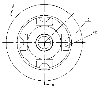
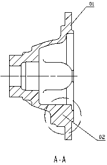
[0034] combined with image 3 to attach Figure 9 , a differential case casting process, it comprises the steps:
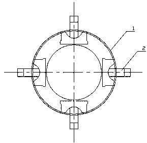
[0035] 1. A core making machine is used to produce a sand core main body 1. The sand core main body 1 is an integrated structure with a casting hole sand column 2 for casting a cross shaft hole on a differential case;
[0036] 2. Dry the sand core main body 1 described in step 1;
[0037] 3. Place the sand core main body 1 after drying in step 2 in the upper and lower molds of the differential case, and then cast the molds according to the conventional casting process;
[0038] Four, finally open the casting mold to obtain the differential case 4 with the cross shaft hole 6 .
[0039] Preferably, the core-making machine is a core-shooting machine that uses a hot box process to make coated sand cores.
[0040] The conventional casting method ...
PUM
 Abstract
Description
Claims
Application Information