
Control system and control method of logging drilling sidewall coring tool

A wall corer and control system technology, applied in wellbore/well components, earthwork drilling, etc., can solve the problems of not being able to issue drilling withdrawal instructions in time, damaging downhole instruments, and unlocking cards.

Active Publication Date: 2015-02-25
BC P INC CHINA NAT PETROLEUM CORP +1
View PDF11 Cites 10 Cited by
  • Summary
  • Abstract
  • Description
  • Claims
  • Application Information

AI Technical Summary

Problems solved by technology

[0005] However, since the maximum output current of the motor drive power supply is much smaller than the stall value of the motor, when the load of the drill bit suddenly increases and the motor current increases rapidly, the drive power supply cannot supply more current to maintain the rotation of the motor, and it will stop feeding the motor itself. Power supply, turn to restart the motor, so that the drill bit stuck engineering accident cannot be found when drilling the core, and the operator cannot make a correct judgment in time, and cannot issue a drill back command to release the jam in time, so that the drill bit is stuck and damaged Downhole Instruments
[0006] Moreover, when the drilling sidewall corer is working downhole, the operator needs to make a decision based on the first pump pressure value, the second pump pressure value displayed on the ground control panel, the working voltage and current of the motor, and the values ​​of various displacement sensors. Comprehensive analysis and judgment can only be carried out before the operation of various control instruments. When the operation is wrong, the hydraulic components will be easily damaged, resulting in engineering accidents.

Method used


Image

  • Control system and control method of logging drilling sidewall coring tool
  • Control system and control method of logging drilling sidewall coring tool
  • Control system and control method of logging drilling sidewall coring tool

Examples


Embodiment approach 1

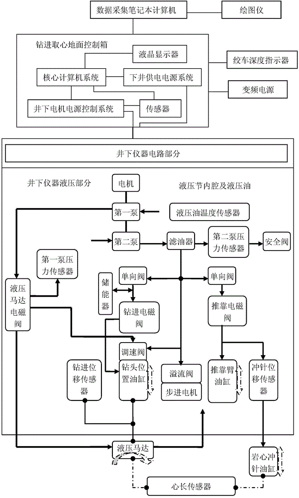
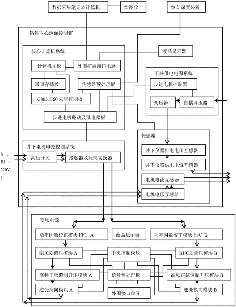
[0062] like figure 1 As shown, the control system of the well logging drilling type sidewall coring device of the present invention includes a data acquisition notebook computer for the real-time recording function of coring data; a plotter for the paper recording function of coring data; Frequency conversion power supply for downhole instrument motor power supply; drilling and coring surface control box for signal processing and data acquisition, as well as downhole instrument status control and power supply; The drawworks depth device of the movement signal; the drilling and coring ground control box obtains the depth, movement direction and speed data of the downhole instrument in the wellbore according to the received movement signal, as real-time information of other coring data. It also includes the hydraulic part of the downhole instrument used for drilling sidewall coring operation and energy transmission; the circuit part of the downhole instrument used for detecting ...

Embodiment approach 2

[0070] When the control system of the logging drilling type borehole wall coring device described in the present invention is working, the coring is completed under the control of the ground control box for drilling and coring, and the method of automatically adjusting the working voltage of the solenoid valve. Such as image 3 as shown,

[0071] First, the ground control box supplies power to complete the initialization process; then the ground control box sets the working safety voltage of the solenoid valve of the downhole instrument; after that, the ground control box supplies power to the downhole instrument, and the circuit part of the downhole instrument completes the initialization process; the downhole instrument uploads the working status to the ground The control box and the ground control box query the working voltage of the solenoid valve in the downhole instrument, and start the process of automatically adjusting the working voltage of the solenoid valve; when th...

Embodiment approach 3

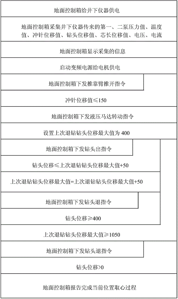
[0073] When the control system of the logging drilling type borehole wall coring device described in the present invention works, the coring is completed by the control of the ground control box for drilling and coring, such as Figure 4 As shown, its overall method steps are as follows.

[0074] First, after the ground control box is powered on, set the maximum safe working current of the motor of the downhole instrument, the maximum power value of the system, the maximum safe working current variation of the motor, the minimum drilling displacement variation ΔS per unit time of the drill bit, and the maximum displacement of the drill bit Smax, etc., the ground control box supplies power to downhole instruments and establishes communication with downhole instruments; then, the ground control box collects the motor operating current, first pump pressure value, and drill bit drilling displacement value instrument status data uploaded by downhole instruments; After the start, th...


PUM


Abstract

The invention discloses a control system of a logging drilling sidewall coring tool. The control system comprises a drilling coring ground control box, a winch depth device, a variable frequency power source, a downhole instrument circuit part and a downhole instrument hydraulic part, wherein data acquisition and feedback control are performed on the coring tool through the drilling coring ground control box, various states of a downhole instrument can be detected in time through the downhole instrument circuit part, the power supply state of a downhole motor and the power supply state of the downhole instrument are monitored through a sensor, and the downhole motor can be adjusted and controlled by processing acquired data and controlling the variable frequency power source. According to a control method, automatic control over coring of the coring tool is achieved through the ground control box, an execution motor can be continuously started, a backup arm expands, the stretching displacement of a punch pin is minimal, the pressure of a second pump is maximal, a hydraulic motor rotates, a drill bit stretches out, the hydraulic motor stops rotating when the drilling displacement reaches the core breaking position, and a series of continuous actions that the core breaking drill bit retreats and is taken back is completed.

Description

technical field [0001] The invention belongs to the field of geological exploration, and relates to controlling a drilling-type borehole wall coring device to drill cores vertically from a downhole destination layer, in particular to a control system and a control method for a drilling-type borehole wall coring device. Background technique [0002] At present, in the Chinese patent 200620008135.3, a drilling type sidewall coring device is proposed, which is composed of a ground control system and a downhole coring system. The cables are connected, the ground control system provides high-voltage, high-current power supply to the motor of the downhole coring system, and then the motor drives the hydraulic pump to provide hydraulic energy to the downhole coring system, and the downhole coring system is manipulated to perform coring; The ground control system is composed of ground pressure regulating cabinet, boosting cabinet, control cabinet and logging winch, which are connect...

Claims


Application Information

Patent Timeline
IPC IPC(8): E21B49/06
CPCE21B49/06
Inventor 王爱新刘文革方旭红田亚锋田丽萍贺海龙陈金宏陈川李珊纪志伟葛海娅张志敏
Owner BC P INC CHINA NAT PETROLEUM CORP
Learn More