Light emitting device

A light-emitting device and technology for emitting red light, applied in the fields of lighting technology, display and optoelectronics, can solve the problems of harsh preparation method, high price, low brightness, etc., and achieve the effects of low cost, improved light-emitting brightness and novel structure.

Active Publication Date: 2015-02-25
朝克夫
View PDF8 Cites 4 Cited by
  • Summary
  • Abstract
  • Description
  • Claims
  • Application Information

AI Technical Summary

Problems solved by technology

The former white LED has better brightness but poor color rendering, or the brightness is not high and the color rendering is better.
In addition, the preparation methods of the nitride and nitrogen oxide fluorescent materials used in these two methods are very harsh, so the price is relatively expensive

Method used


Image

  • Light emitting device
  • Light emitting device
  • Light emitting device

Examples


Embodiment 1

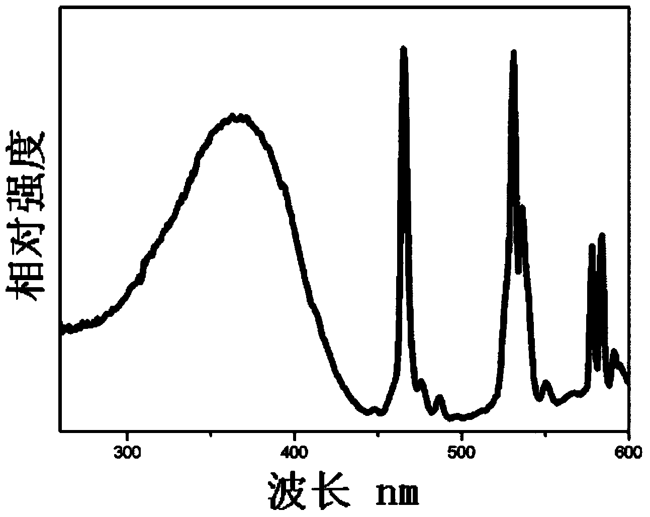
[0033] Example 1: Ca 0.8 Li 0.1 MoO 4-x f x : Eu 0.1 Preparation of fluorescent materials

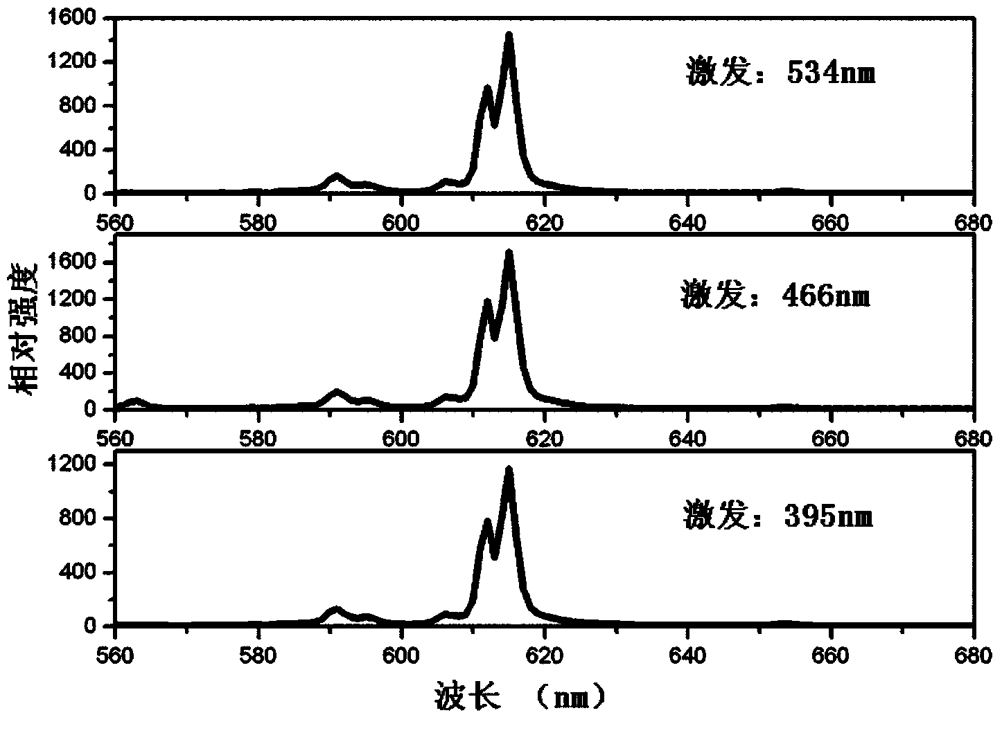
[0034] Weigh various raw materials CaCO according to stoichiometric composition 3 , Li 2 CO 3 , Eu 2 o 3 , MoO 3 , NH 4 F, where NH is weighed 4 The molar masses of F are 0, 0.01, 0.02, 0.05, 0.08, 0.10, that is, the x values ​​are 0, 0.01, 0.02, 0.04, 0.08, 0.10. After the above 6 groups of raw materials are fully ball-milled and mixed evenly, put them into a 99% porcelain crucible, keep warm at 500°C for 5 hours in an air atmosphere, then raise the temperature to 850°C and keep warm for 4 hours, cool the sintered body, crush, sieve, and classify. The chemical composition in the present invention is obtained as Ca 0.8 Eu 0.1 Li 0.1 MoO 4 : NH 4 F fluorescent material. where Ca 0.8 Li 0.1 MoO 3.92 f 0.08 : Eu 0.1 The excitation spectrum of figure 1 As shown, the emission spectra under different excitation light are as figure 2 Its maximum emission is shown at 6...

Embodiment 2

[0035] Example 2: Ca 0.72 Li 0.1 MoO 4-x f x : Eu 0.96 SM 0.04 Preparation of fluorescent materials

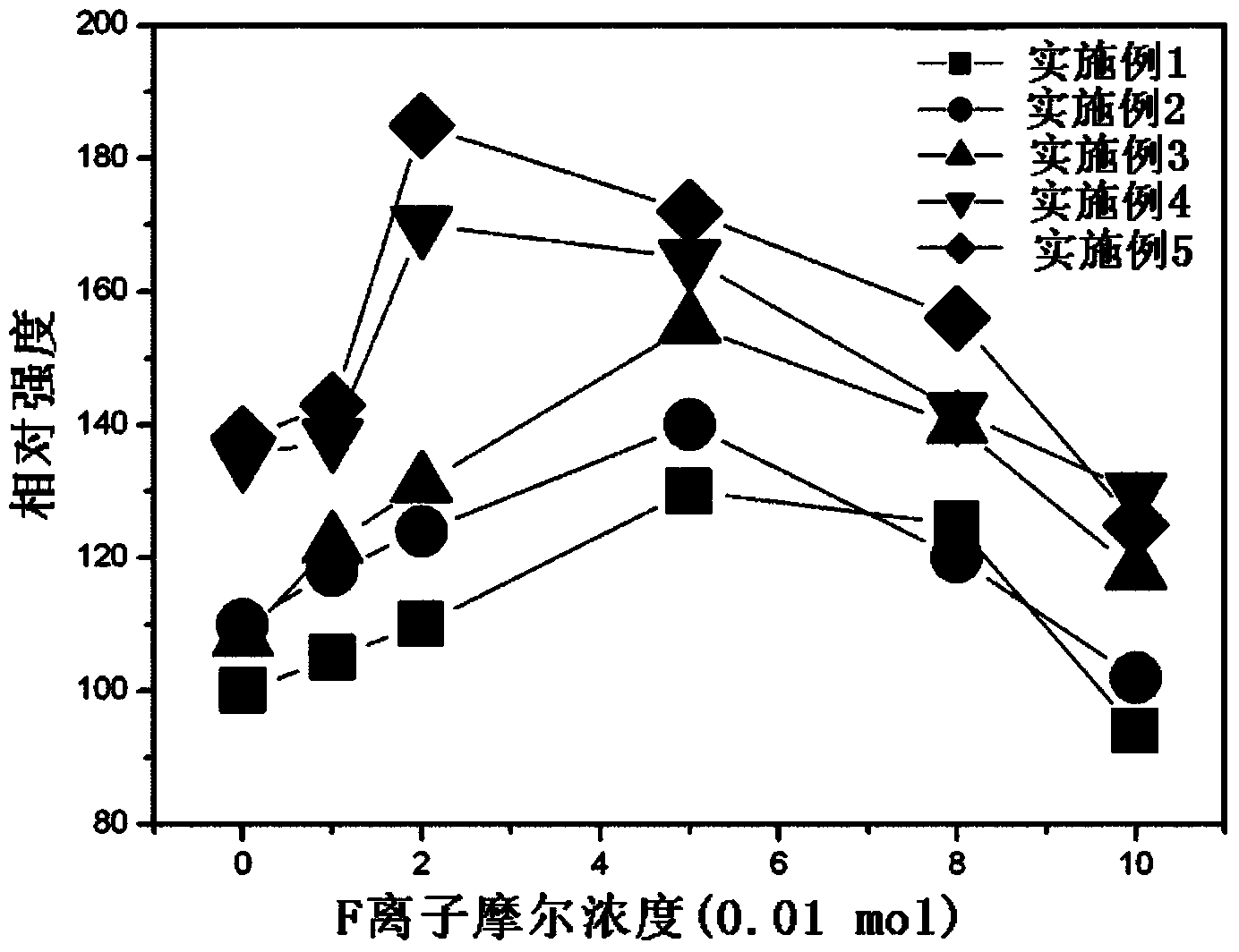
[0036] Weigh various raw materials CaCO according to stoichiometric composition 3 , Li 2 CO 3 , Eu 2 o 3 , MoO 3 , SmO 3 , NH 4 F, where NH is weighed 4 The molar masses of F are 0, 0.01, 0.02, 0.05, 0.08, 0.10, that is, the x values ​​are 0, 0.01, 0.02, 0.04, 0.08, 0.10. After the above 6 groups of raw materials are fully ball-milled and mixed evenly, put them into a 99% porcelain crucible, keep warm at 500°C for 5 hours in an air atmosphere, then raise the temperature to 850°C and keep warm for 4 hours, cool the sintered body, crush, sieve, and classify. The chemical composition in the present invention is obtained as Ca 0.72 Li 0.1 O 4-x f x : Eu 0.96 SM 0.04 fluorescent material. Its excitation and emission spectral characteristics are basically consistent with those of Example 1. Different content of NH 4 The effect of F on the luminous intensity at...

Embodiment 3

[0037] Example 3: LiMo 2 o 8-x f 2x : Preparation of Eu fluorescent material

[0038] Weigh various raw materials CaCO according to stoichiometric composition 3 , Li 2 CO 3 , Eu 2 o 3 , MoO 3 , LiF, where the molar mass of LiF is weighed as 0, 0.01, 0.02, 0.05, 0.08, 0.10, that is, the x value is 0, 0.01, 0.02, 0.04, 0.08, 0.10. After the above 6 groups of raw materials are fully ball-milled and mixed evenly, put them into a 99% porcelain crucible, keep warm at 500°C for 5 hours in an air atmosphere, then raise the temperature to 850°C and keep warm for 4 hours, cool the sintered body, crush, sieve, and classify. Obtaining the chemical composition in the present invention is LiMo 2 o 8-x f 2x : Eu fluorescent material. Its excitation and emission spectral characteristics are basically consistent with those of Example 1. The influence of different contents of LiF on the luminous intensity at 615nm is as follows: image 3 Shown in line 3.


PUM

PropertyMeasurementUnit
wavelengthaaaaaaaaaa

Abstract

The invention belongs to the field of illumination technologies, display and photoelectrons, and relates to a light emitting device. The light emitting device is made of fluorescent materials and can emit red light when motivated by light with the wavelength ranging from 240 nm to 540 nm. The light emitting device comprises at least two kinds of light emitting elements and a light emitting layer. The light emitting elements are used as laser light sources and are semiconductor light emitting chips with the emission spectrum peak value ranging from 240 nm to 540 nm in the ultraviolet-blue and green light area range. The light emitting layer comprises the fluorescent materials which receive the light emitted by the light emitting elements and emit light. The fluorescent materials comprise the fluorescent materials emitting red light and the fluorescent materials emitting yellow light. The two kinds of fluorescent materials are mixed to coat the two semiconductor light emitting chips respectively. The fluorescent materials emitting red light can convert the emitted light of the light emitting elements into light with at least one peak value wavelength ranging from 600 nm to 700 nm. According to the fluorescent materials, the color development performance and emitted light brightness of an existing white light LED can be improved, and multi-chip structural style is novel and reliable.

Description

technical field [0001] The invention belongs to the fields of lighting technology, display and optoelectronics, and relates to a light-emitting device including a fluorescent material that can be excited by light with a wavelength range of 240-540nm to emit red light. Background technique [0002] Light Emitting Diode (Light Emitting Diode) is an energy conversion device that can convert electrical energy into light energy. It is the future light source of the world and is considered to be one of the most promising high-tech fields in the 21st century. As a new lighting technology, LED is triggering a revolution in the lighting field due to its long service life, low power consumption, flexible application, green environmental protection, convenient adjustment, and fast light response. With the rapid development of blue, purple and ultraviolet LEDs in recent years, it is possible for LEDs to replace traditional incandescent and fluorescent lamps for lighting. [0003] At pr...

Claims


Application Information

Patent Timeline
Patent Type & Authority Applications(China)
IPC IPC(8): H01L33/50C09K11/68C09K11/78C09K11/86
CPCH01L33/504H01L33/54C09K11/597C09K11/685C09K11/77H01L2933/005H01L2933/0041H01L2224/8592H01L2924/181H01L2224/48091H01L2224/48247H01L2224/48257H01L2224/49107H01L2224/49113H01L2224/73265Y02B20/00H01L2924/00012H01L2924/00014
Inventor 朝克夫那日苏特古斯
Owner 朝克夫
Why Eureka
Try Eureka