A blast furnace elevated pipeline wet injection system and method

A pipeline and high-level technology, which is applied in the field of blast furnace high-level pipeline wet injection system, can solve the problems of high conveying pressure and large pipeline loss, achieve uniform and rapid injection, reduce quantity and labor intensity, and improve injection efficiency Effect

Active Publication Date: 2016-04-06
北京联合荣大工程材料股份有限公司
View PDF4 Cites 0 Cited by
  • Summary
  • Abstract
  • Description
  • Claims
  • Application Information

AI Technical Summary

Problems solved by technology

Because of the high height, the conveying pressure must be high, the wear of the powder in the pipeline will be great, and the loss of the pipeline will be great.

Method used


Image

  • A blast furnace elevated pipeline wet injection system and method
  • A blast furnace elevated pipeline wet injection system and method
  • A blast furnace elevated pipeline wet injection system and method

Examples


Embodiment 1

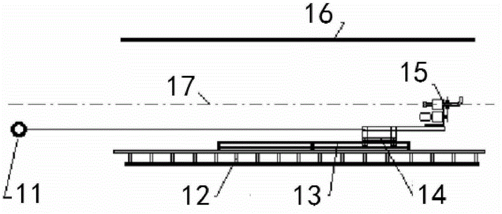
[0024] Embodiment 1: as figure 1 , figure 2 , image 3 and Figure 4 As shown, a high-level pipeline wet injection system for a blast furnace includes a set of high-level conveying equipment, a set of collecting equipment and pumping devices, and a set of rotary injection manipulators used in the pipelines of the in-pipeline rotary injection manipulator device.

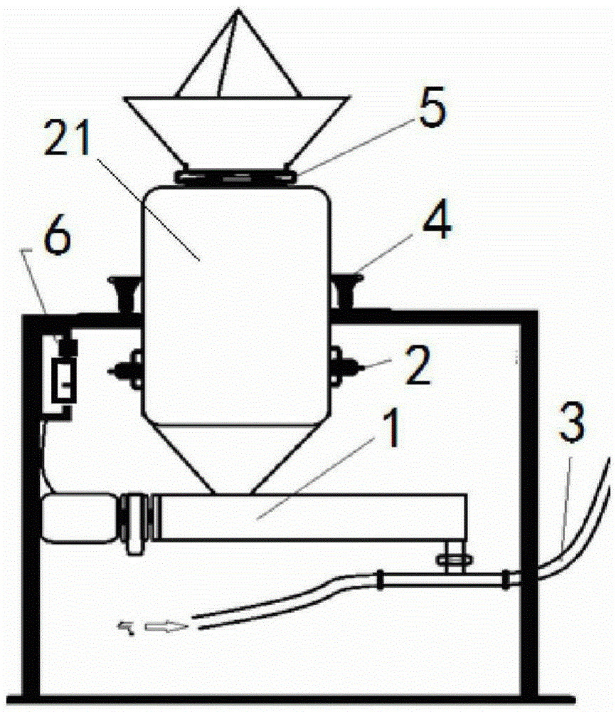
[0025] The high-level conveying equipment includes a material tank system with a feed valve and a discharge screw, a pneumatic conveying system, a gravity monitoring system for the state of the material in the tank, a shock and vibration system to prevent the sticky material on the inner wall of the tank, and a PLC for controlling the screw discharge speed Electric control system.

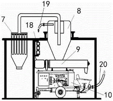
[0026] The collection equipment and pumping device include a cyclone collection cylinder and a belt dust collection mechanism. The lower part of the cyclone dust collector is the collection bin, and the refractory material from the co...

Embodiment 2

[0032] Embodiment 2: as figure 1 , figure 2 , image 3 and Figure 4 As shown, a blast furnace high-level pipeline wet injection system, the gas material pipeline 3 of the high-level conveying equipment 100 is connected to the continuous mixer 9 of the collection equipment and the pumping device 200; the uniformly stirred wet material pipeline of the collection equipment and the pumping device 200 20 is connected to the rotary spray gun 15 of the rotary injection manipulator device 300 in the pipeline.

[0033] The discharge screw device 1 is connected to the gas pipeline 3 and the feed bin 21, the bin mouth of the feed bin 21 is connected to the feed valve 5, and the gravity monitoring device 4 is installed in the middle of the feed bin 21 and fixed on the shell, and the impact vibration The device 2 is connected to the middle and lower part of the feed bin 21, the first PLC control device 6 is fixed on the casing, and the first PLC control device 6 is connected to the di...


PUM


Abstract

The invention discloses a blast furnace high-order pipeline wet-method ejection system and method, belonging to the technical field of blast furnace high-order pipeline ejection construction techniques and equipment. The blast furnace high-order pipeline wet-method ejection system comprises a set of high-order conveying equipment, a set of collecting equipment, a pumping device and a set of rotation ejection manipulator used in a pipeline, wherein the high-order conveying equipment comprises a material tank system with a feeding valve and a discharge spiral, a power conveying system, and a PLC electric control system for controlling the discharge speed of the spiral; a high-order collecting system comprises a cyclone collection cylinder and a belt type dust collection mechanism; a fire-resistant powder material collected through cyclone dust collection is directly fed into a continuous stirring machine; the rotation ejection manipulator used in the pipeline comprises a rotation ejection manipulator and a track system which ensures that the manipulator can move in the length direction of the pipeline inside the pipeline and can be detached and assembled. By adopting the blast furnace high-order pipeline wet-method ejection system and the blast furnace high-order pipeline wet-method ejection method, material conveying and wet method injection operation in ultra-high ultra-far distance (such as a blast furnace lifting tube or a descending tube) can be achieved, the manipulator can be externally and remotely controlled to eject, and thus the number of operators is reduced, and the working intensity of the operators is alleviated.

Description

technical field [0001] The invention relates to a blast furnace high-level pipeline wet injection system and method, and belongs to the technical field of blast furnace pipeline injection construction technology and equipment. Background technique [0002] Blast furnace piping system includes gas riser, downcomer and gravity dust collector. The lining must be coated with refractory material. The traditional construction method is dry or semi-dry manual spraying, that is, the dry powder refractory material is transported to the nozzle of the spray gun by pneumatic conveying, and then a sufficient amount of water is added to the nozzle, and the dry powder is mixed with water and sprayed out of the spray gun and attached to the pipe wall. [0003] In this operation, there is a large loss of material rebound, the quality of the wall material is difficult to guarantee, the working environment is extremely dusty, the labor intensity of the workers is extremely high, and the cons...

Claims


Application Information

Patent Timeline
Patent Type & Authority Patents(China)
IPC IPC(8): C21B7/00C21B7/06
CPCC21B7/00C21B7/06
Inventor 章荣会于运祥刘贯重
Owner 北京联合荣大工程材料股份有限公司
Why Eureka
Try Eureka