
Transistor and transistor manufacturing method

A manufacturing method and transistor technology, applied in the direction of transistors, semiconductor/solid-state device manufacturing, electric solid-state devices, etc., can solve the problems of reduced electron concentration, reduced current flowing between drain-source electrodes, high plasma reactivity, etc., and achieve insulation destruction The effect of suppressing the reduction of current due to high voltage

Inactive Publication Date: 2015-03-04
MURATA MFG CO LTD
View PDF9 Cites 0 Cited by
  • Summary
  • Abstract
  • Description
  • Claims
  • Application Information

AI Technical Summary

Problems solved by technology

[0021] However, when using the above O 2 plasma to form the gate insulating film 107, due to O 2 Plasma has high reactivity, so the semiconductor layer 102 is easily damaged
Therefore, there is a problem that the electron concentration in the damaged semiconductor layer 102 decreases, and the current flowing between the drain-source electrodes of the transistor 200 decreases.

Method used


Image

  • Transistor and transistor manufacturing method
  • Transistor and transistor manufacturing method
  • Transistor and transistor manufacturing method

Examples


Embodiment Construction

[0031] An example of a mode for implementing the present invention will be described below with reference to the drawings.

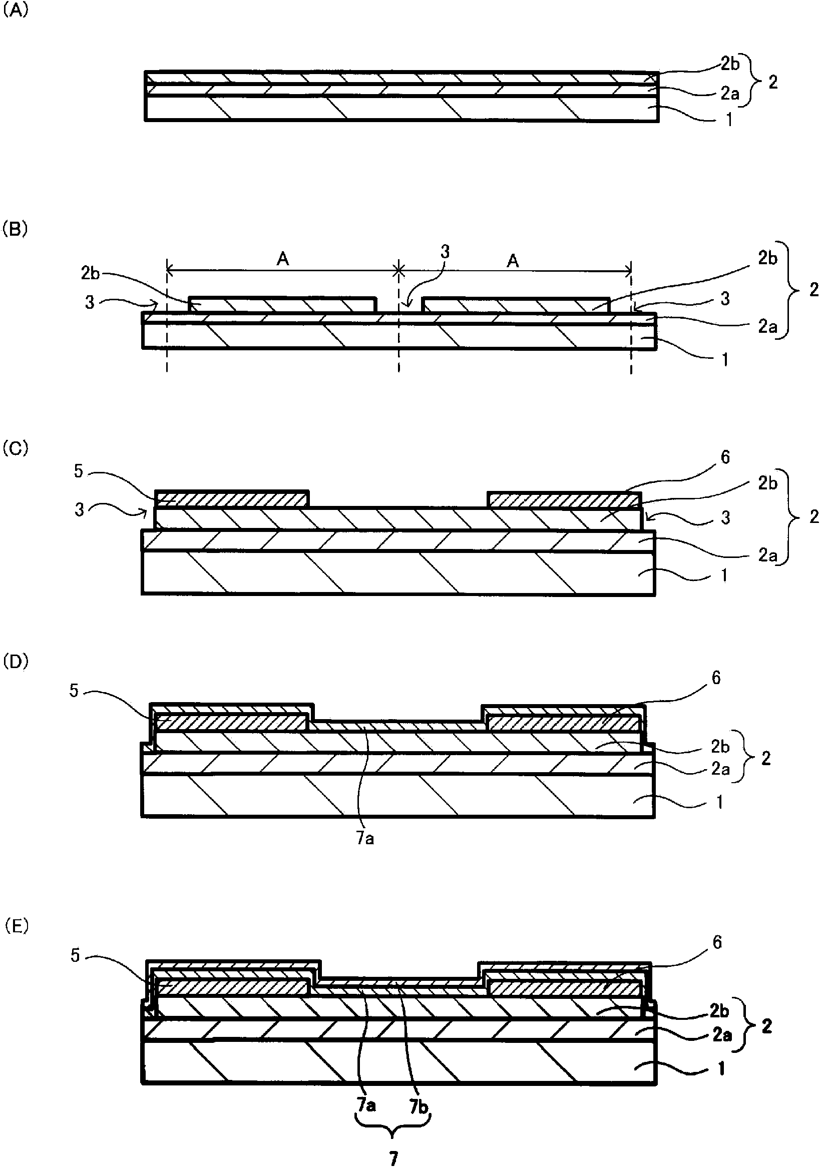
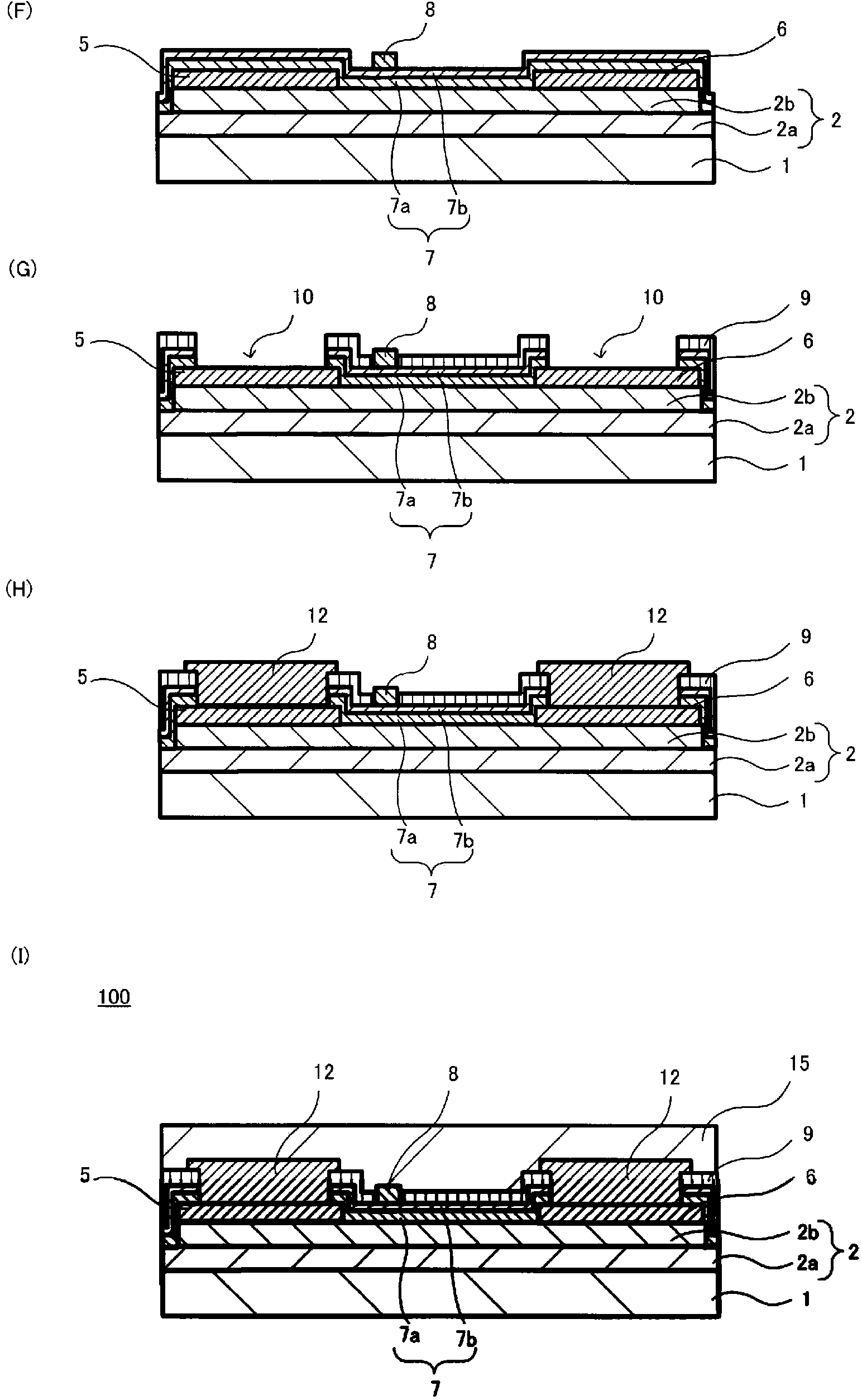
[0032] exist figure 2 (I) shows a cross-sectional view of the transistor 100 according to the embodiment of the present invention.

[0033] The transistor 100 includes a semiconductor layer 2 made of a gallium nitride layer 2 a and an aluminum gallium nitride layer 2 b on a substrate 1 made of gallium nitride, silicon, silicon carbide, or the like.

[0034] On the semiconductor layer 2, a source electrode 5 and a drain electrode 6 made of a material including titanium and aluminum are formed.

[0035] On the source electrode 5 and the drain electrode 6, a connection electrode 12 made of a material containing gold or the like is formed.

[0036] On a part of the semiconductor layer 2, a first gate insulating film 7a made of aluminum oxide or the like is formed. The first gate insulating film 7 a contains at least one of hydrogen atoms and carbon atoms...


PUM


Abstract

The purpose of the present invention is to provide a transistor, which has a high breakdown voltage of a gate insulating film, while suppressing deterioration of a current flowing between drain / source electrodes. A transistor (100) is characterized in being provided with: a semiconductor layer (2); a gate insulating film (7) formed on the semiconductor layer (2); a gate electrode (8) formed on the gate insulating film (7); and a source electrode (5) and a drain electrode (6), which are formed on the semiconductor layer (2) with the gate electrode (8) sandwiched between the electrodes. The transistor is also characterized in that the concentration of an impurity contained in the gate insulating film (7) is reduced toward the gate insulating film (7) surface on the gate electrode (8) side from the gate insulating film (7) surface on the semiconductor layer (2) side.

Description

technical field [0001] The present invention relates to a transistor including a gate insulating film and a method for manufacturing the transistor. Background technique [0002] Conventionally, for example, a transistor disclosed in Patent Document 1 (JP-A-2010-98141) has been used as a signal amplifier in an electronic circuit. [0003] Figure 4 An example of a conventional transistor is shown. also, Figure 4 It is a cross-sectional view of a conventional transistor 200 . [0004] Figure 4 The illustrated transistor 200 includes a semiconductor layer 102 including a GaN layer 102 a and an AlGaN layer 102 b on a substrate 101 . [0005] On the semiconductor layer 102, a source electrode 105 and a drain electrode 106 are formed. [0006] A connection electrode 112 is formed on the source electrode 105 and the drain electrode 106 . [0007] A gate insulating film 107 is formed on a part of the semiconductor layer 102 . [0008] A gate electrode 108 is formed on a part...

Claims


Application Information

Patent Timeline
Patent Type & Authority Applications(China)
IPC IPC(8): H01L21/336H01L21/316H01L29/78
CPCH01L2924/0002H01L29/7786H01L21/02274H01L29/2003H01L21/561H01L21/0228H01L23/291H01L29/517H01L21/022H01L29/66462H01L21/02178H01L23/3171H01L21/823462H01L2924/00H01L29/513H01L27/088H01L29/408H01L29/66477H01L29/78
Inventor 荒木圣人桥本正太郎高尾将和
Owner MURATA MFG CO LTD
Learn More