
Molten slag dry granulation and waste heat recovery system

A waste heat recovery system and dry granulation technology, applied in the field of metallurgical energy saving, can solve the problems of high temperature resistance requirements of slag particle conveying equipment, high temperature of slag particles, hardening and agglomeration, etc., to reduce the temperature of slag particles, reduce The effect of high temperature resistance and lower requirements

Inactive Publication Date: 2015-03-11
CHONGQING CISDI THERMAL & ENVIRONMENTAL ENG CO LTD
View PDF5 Cites 6 Cited by
  • Summary
  • Abstract
  • Description
  • Claims
  • Application Information

AI Technical Summary

Problems solved by technology

[0003] In the existing technology, the slag treatment process is mostly divided into two functional units: dry granulation and waste heat recovery, but the temperature of the slag particles at the outlet of the dry granulation unit is high, which not only requires extremely high temperature resistance of the slag particle conveying equipment , and there is a risk of remelting and agglomeration of high-temperature slag particles

Method used


Image

  • Molten slag dry granulation and waste heat recovery system
  • Molten slag dry granulation and waste heat recovery system
  • Molten slag dry granulation and waste heat recovery system

Examples


Embodiment 1

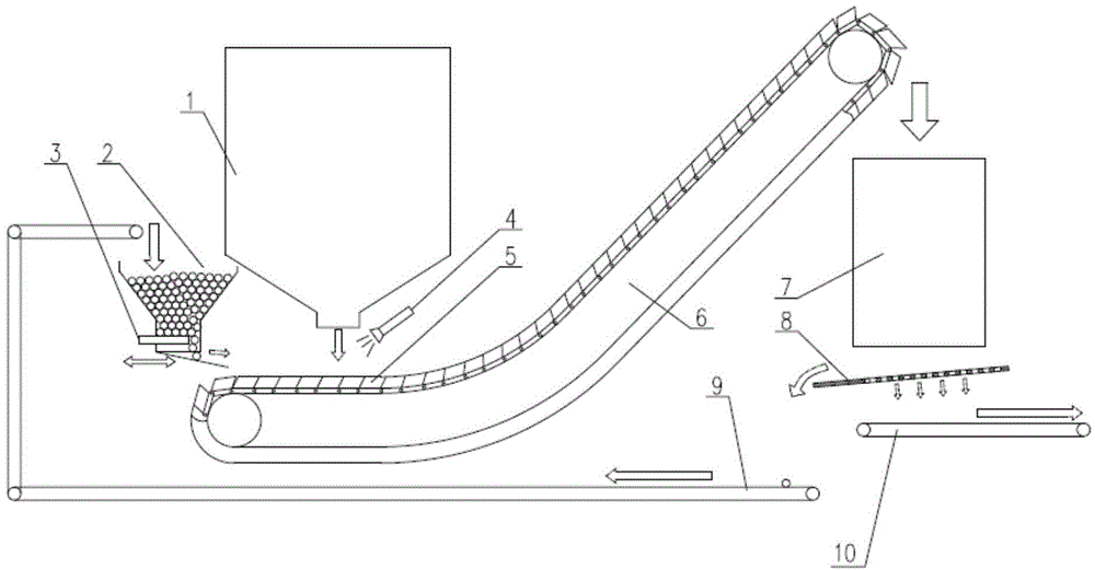
[0022] Such as figure 2 As shown, the two dry granulation units 1 transport slag particles to the same waste heat recovery unit 7 through the chain bucket conveyor 6 respectively. The dry granulation unit 1 and the waste heat recovery unit 7 are located at the same level, and the chain bucket conveyor 6. Convey horizontally and then upwardly, with an inclination angle of 20 to 30 degrees; the cold material bin 2 is equipped with low-temperature slag particles with a large particle size, and the high-temperature slag is mixed with the high-temperature slag at the outlet of the granulation unit 1 through the flow adjustment device 3 at a suitable flow rate. The slag particles impact and mix with each other, and fall into the hopper 5 of the chain bucket conveyor 6; after the waste heat recovery unit 7, a screening device 8 is used to separate the slag particles with a diameter of 3 to 5 mm, and the slag particles with a diameter of 3 to 5 mm are separated through the cold materi...

Embodiment 2

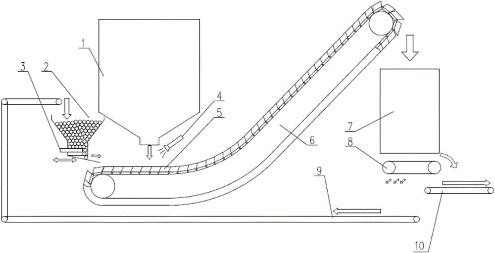
[0024] Such as image 3 As shown, the dry granulation unit 1 and the waste heat recovery unit 7 are located on the same horizontal plane, connected by the chain bucket conveyor 6, and the chain bucket conveyor 6 is first conveyed horizontally and then inclined upward, with an inclination angle of 20-30 degrees; cold material The bin 2 is equipped with steel balls, which fall into the hopper 5 of the chain bucket conveyor 6 at a suitable flow rate through the flow regulating device 3, and spread on the bottom of the hopper 5; when the temperature measuring device 4 measures the temperature of the slag particles 11 higher than the set When the value is fixed, each hopper is filled with multi-layer steel balls 12, and when the measured temperature is lower than the set value, the amount of steel balls loaded in the hopper is reduced; the mixture of steel balls and slag particles recovers heat through the waste heat recovery unit 7 Finally, when the temperature drops below 150°C, ...


PUM


Abstract

The invention relates to a molten slag dry granulation and waste heat recovery system, and belongs to the technical field of metallurgy energy saving. The system comprises a molten slag dry granulation unit 1 and a waste heat recovery unit 7, wherein the molten slag dry granulation unit 1 is connected with the waste heat recovery unit 7 through a bucket chain conveyor 6; a cold material bin 2 is arranged above the head part of the bucket chain conveyor 6 and can unload a cold material into the conveyor; a flow adjustment device 3 is arranged at the bottom of the cold material cabin 2, and the flow of the cold material is adjusted by the flow adjustment device 3, so that the flow of the cold material is controllable. According to the system, the cold material and granulated slag particles are mutually mixed; the temperature of the slag particles is reduced; the re-melting of the slag particles is avoided; the requirement for the high temperature resistance of conveying machinery is reduced; the slag particles are transported by using the bucket chain conveyor; the molten slag dry granulation unit and the waste heat recovery unit are arranged conveniently and flexibly according to actual situations; a slag particle temperature control method is provided, so that the temperature of the materials at the inlet of the waste heat recovery unit basically keeps stable.

Description

technical field [0001] The invention belongs to the technical field of metallurgy and energy saving, and relates to a slag dry granulation and waste heat recovery system. Background technique [0002] According to the "Basic Situation of Comprehensive Utilization of Iron and Steel Slag in 2012" issued by the Metallurgical Slag Development and Utilization Working Committee of China Scrap Iron and Steel Application Association, the production of blast furnace slag in my country in 2012 was 220 million tons. The discharge temperature of blast furnace slag is above 1400°C, which is high-quality heat energy. Calculated based on the sensible heat of 1.8GJ per ton of slag, the annual available heat energy of blast furnace slag is 3.96×10 8 GJ, equivalent to 13.53 million tons of standard coal. However, at present, blast furnace slag in my country is mainly processed by water quenching, which not only wastes water resources, but also does not recycle the heat of blast furnace slag....

Claims


Application Information

Patent Timeline
IPC IPC(8): C21B3/06
CPCC21B3/06C21B2200/00F27D17/004Y02W30/50
Inventor 陈君李朋张道明
Owner CHONGQING CISDI THERMAL & ENVIRONMENTAL ENG CO LTD
Learn More