Narrow-linewidth and long-time-stable frequency dye laser and frequency stabilization method thereof

A dye laser and frequency stabilization technology, applied in the field of lasers, can solve the problems of long-term frequency drift, narrow line width, and output laser line width not narrowed, etc., to achieve convenient implementation, strong scalability, and simple principle Effect

Active Publication Date: 2015-03-11
EAST CHINA NORMAL UNIV
View PDF3 Cites 10 Cited by
  • Summary
  • Abstract
  • Description
  • Claims
  • Application Information

AI Technical Summary

Problems solved by technology

Although ring dye lasers with complex structures can output single or multi-longitudinal mode lasers, they still have the disadvantage of large long-term frequency drift, and when there is no feedback control, the linewidth of the output laser can reach tens of MHz.
At present, dye lasers usually use the frequency stabilization method of PDH to lock the dye laser on a relatively stable reference cavity, which narrows the linewidth of the dye laser and improves the short-term frequency stability, but the long-term frequency drift still remains unsolved
The dye laser can also be directly locked to the transition line of the iodine molecule or atom, and the long-term drift of the laser is solved, but the line width of the output laser is not narrowed, and the output laser wavelength cannot be continuously tuned under the locking condition
[0004] In order to solve the technical problem that dye lasers in the prior art cannot maintain narrow linewidth and long-term frequency stability at the same time, the present invention proposes a brand-new dye laser with narrow linewidth and long-term frequency stability and its frequency stabilization method, so that the dye laser The frequency long-term drift and laser linewidth are controlled

Method used


Image

  • Narrow-linewidth and long-time-stable frequency dye laser and frequency stabilization method thereof
  • Narrow-linewidth and long-time-stable frequency dye laser and frequency stabilization method thereof
  • Narrow-linewidth and long-time-stable frequency dye laser and frequency stabilization method thereof

Examples


Embodiment Construction

[0029] The present invention will be further described in detail in conjunction with the following specific embodiments and accompanying drawings. The process, conditions, experimental methods, etc. for implementing the present invention, except for the content specifically mentioned below, are common knowledge and common knowledge in this field, and the present invention has no special limitation content.

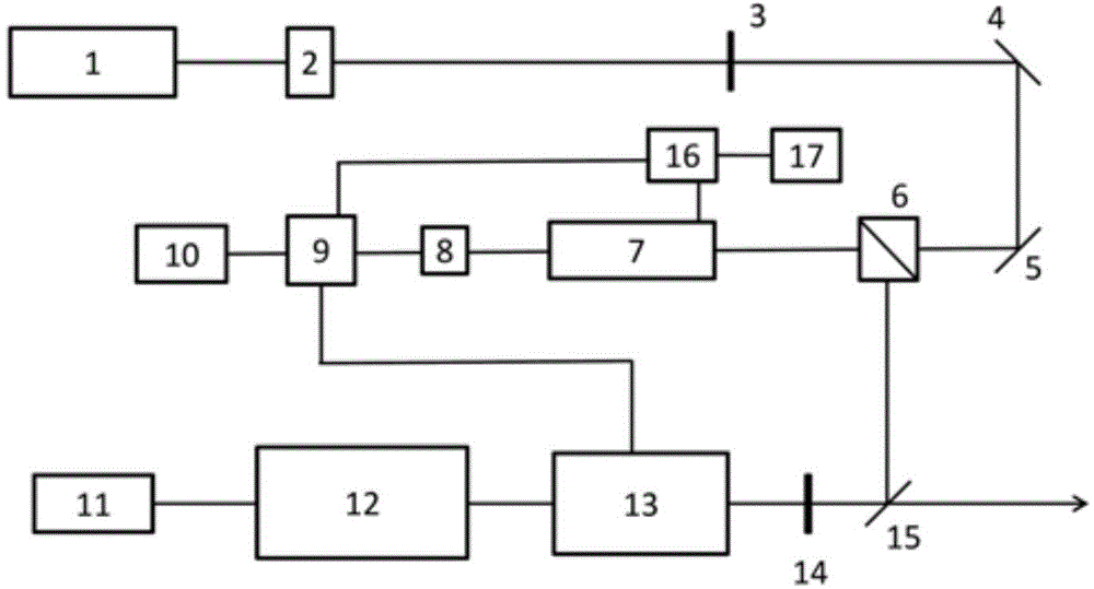
[0030] Such as figure 1 As shown, the dye laser with narrow linewidth and long-term frequency stability includes: a reference laser generator, a dye laser, a reference cavity 13, a polarization beam splitter 6, a transmission cavity 7, an optical detector 8, a data acquisition card 9, and a processor 10. Signal adder 16 and function generator 17;

[0031] The reference laser generator includes a reference laser 1, an optical isolator 2, a first half-wave plate 3, a first mirror 4, and a second mirror 5; the reference laser beam output by the reference laser 1 is input to ...


PUM


Abstract

The invention discloses a narrow-linewidth and long-time-stable frequency dye laser. The narrow-linewidth and long-time-stable frequency dye laser includes a reference-used laser generator, a dye laser, a reference cavity, a polarization beam splitter, a transmission cavity, a light detector, a data acquisition card, a processor, a signal adder and a function generator. According to the narrow-linewidth and long-time-stable frequency dye laser of the invention, two kinds of frequency stabilization methods are combined together to generate a narrow-linewidth and long-time-stable frequency laser beam, and the linewidth of the laser beam is 200kHz, and the frequency long-time drift of the laser beam is smaller than 2MHz. The narrow-linewidth and long-time-stable frequency dye laser of the invention has the advantages of simple circuit design, convenient realization and high scalability. The invention also provides a frequency stabilization method of the dye laser and is suitable for improving the long-time stability of the frequency of any dye lasers.

Description

technical field [0001] The invention belongs to the technical field of lasers, and in particular designs a dye laser with narrow line width and long-term frequency stability and a frequency stabilization method thereof. Background technique [0002] Since the appearance of lasers, since many experiments and occasions require the use of lasers with high frequency stability, the frequency stabilization technology of lasers has always been one of the technologies that people pay attention to. At present, people have developed many kinds of laser frequency stabilization technologies with different principles, such as atomic molecular saturation absorption frequency stabilization technology, PDH frequency stabilization technology and so on. Among them, the saturation absorption frequency stabilization technology can only stabilize the laser on the absorption line of specific atoms and molecules, and can achieve long-term stability of the laser frequency; while the PDH frequency s...

Claims


Application Information

Patent Timeline
Patent Type & Authority Applications(China)
IPC IPC(8): H01S3/20H01S3/13
Inventor 戴大鹏夏勇方银飞尹燕宁杨秀秀李兴佳杜向丽张慧徐素鹏印建平
Owner EAST CHINA NORMAL UNIV
Why Eureka
Try Eureka