Antenna and mobile terminal

A mobile terminal and antenna technology, applied in the field of antennas, can solve problems such as difficulty in ensuring product consistency, affecting antenna debugging work, and increasing antenna power consumption, and achieve the effects of improving antenna efficiency, reducing power consumption, and reducing antenna space.

Inactive Publication Date: 2015-03-11
HUAWEI DEVICE CO LTD
View PDF11 Cites 11 Cited by
  • Summary
  • Abstract
  • Description
  • Claims
  • Application Information

AI Technical Summary

Problems solved by technology

[0003] It is difficult for the antennas in the prior art to increase the bandwidth while reducing the size, and it is impossible to guarantee high efficiency in both high-frequency and low-frequency bands. In order to increase the bandwidth and improve the efficiency of the antenna, the usual method is to The matching circuit of lumped elements (series capacitors and parallel inductors) is added to the electrical circuit to increase the low-frequency bandwidth, but the lumped elements are affected by the m

Method used


Image

  • Antenna and mobile terminal
  • Antenna and mobile terminal
  • Antenna and mobile terminal

Examples


Embodiment 1

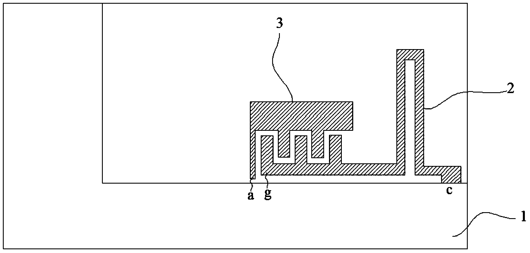
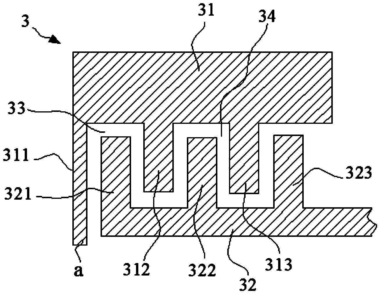
[0058] refer to figure 1 , figure 1 It is a specific embodiment of an antenna according to the embodiment of the present invention. The antenna described in this embodiment is located on a printed circuit board 1. The antenna includes a first radiator 2 and an interdigitated capacitor 3. The distance between the interdigitated capacitor 3 and the second One end of a radiator 2 is provided with a feed point a, the other end of the interdigitated capacitor 3 is electrically connected to the first radiator 2, the free end of the first radiator 2 is provided with a first grounding point c, and the first radiator 2 The bending is in a convex structure, and the length of the first radiator 2 is a predetermined value. The first radiator 2 and the interdigitated capacitor 3 are used to generate the first resonant frequency f1.

[0059] The antenna provided by the embodiment of the present invention includes a first radiator 2 and an interdigitated capacitor 3. A feeding point a is p...

Embodiment 2

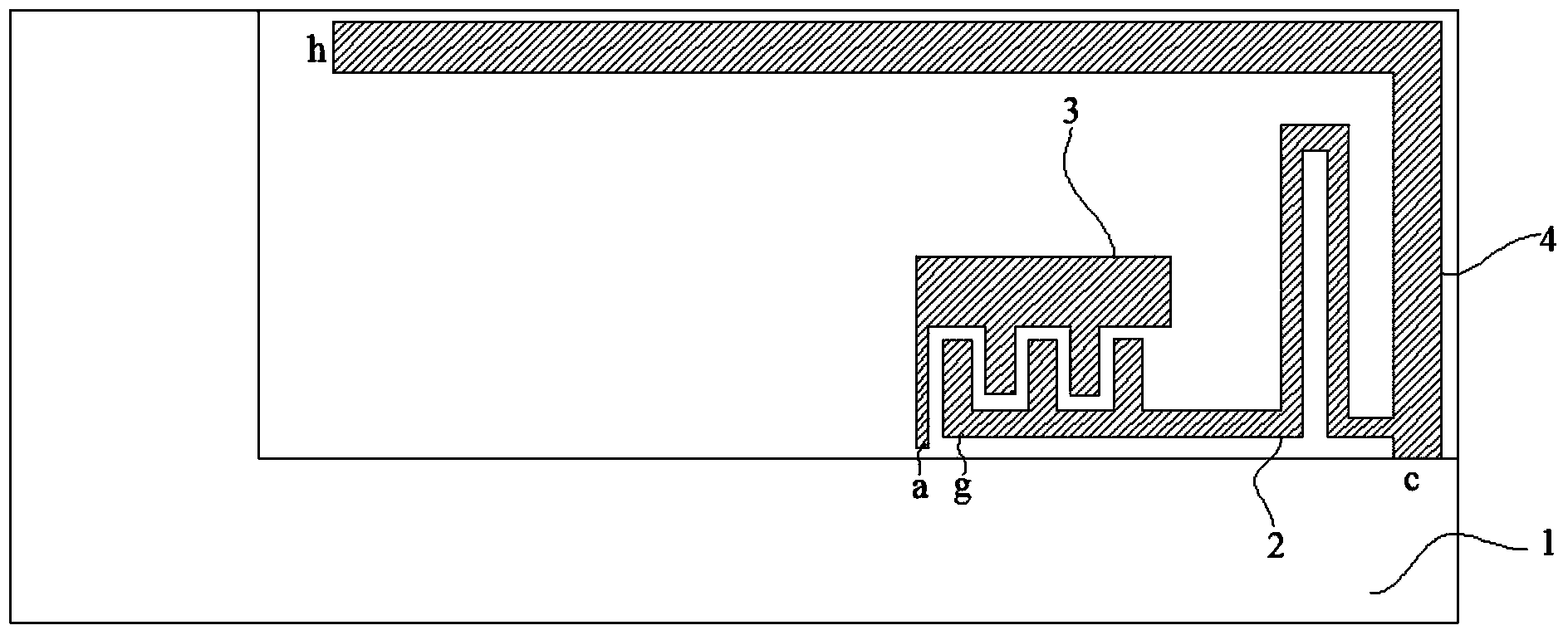
[0080] refer to Figure 9 , the embodiment of the present invention is aimed at the antenna described in the first embodiment, and the antenna described in the first embodiment is according to Figure 8 The layout shown was set up as a test structure, and both simulation and actual tests were performed.

[0081] Such as Figure 9 As shown, an antenna K1 and an antenna K2 are arranged on a printed circuit board 1 with a size of 172mm×145mm. Both the antenna K1 and the antenna K2 are the antennas described in Embodiment 1, and the headroom of the antenna K1 is 20mm×55mm, and the space of the antenna K2 is The headroom is 20mm×50mm, and the antenna includes: a first radiator 2, an interdigitated capacitor 3, an L-shaped second radiator 4, a "匚"-shaped third radiator 5 and a fourth radiator 6.

[0082] Wherein, the interdigitated capacitor 3 includes the first coupling part and the second coupled part, the end of the interdigitated capacitor 3 far away from the first radiator 2...

Embodiment 3

[0087] Such as Figure 13 As shown, the embodiment of the present invention is aimed at the antenna described in Embodiment 1, and the antenna described in Embodiment 1 is according to Figure 11 The layout mode shown is set, the simulation test and the actual test are carried out.

[0088] refer to Figure 13 Antenna K1 and antenna K2 are set on a printed circuit board 1 with a size of 120mm×120mm. Both antenna K1 and antenna K2 are the antennas described in Embodiment 1, and the clearances of antenna K1 and antenna K2 are both 20mm×60mm, so The antenna includes: a first radiator 2, an interdigitated capacitor 3, an L-shaped second radiator 4, a "匚"-shaped third radiator 5 and a fourth radiator 6.

[0089] Wherein, the interdigitated capacitor 3 includes the first coupling part and the second coupled part, the end of the interdigitated capacitor 3 far away from the first radiator 2 is provided with a feeding point a, and one end of the first radiator 2 is connected to the s...


PUM


Abstract

The invention discloses an antenna and a mobile terminal, relates to the technical field of antennas, and aims to reduce the space of the antenna, increase the bandwidth of the antenna, and improve the efficiency of the antenna. The antenna comprises a first radiator and an interdigital capacitor, one end of the interdigital capacitor, far away from the first radiator, is provided with a feeding point, the other end of the interdigital capacitor is electrically connected with the first radiator, a free end of the first radiator is provided with a first grounding point, the first radiator bends to form a protruding structure, and the length of the first radiator satisfies a preset value.

Description

technical field [0001] The present invention relates to the technical field of antennas, in particular to an antenna and a mobile terminal. Background technique [0002] Antenna is a device used by radio equipment to receive and transmit electromagnetic wave signals, and with the advent of the fourth-generation mobile communication, the bandwidth requirements for terminal products are also getting higher and higher. Wireless terminals with multi-mode (GSM / WCDMA / CDMA / LTE) and receive diversity technology are the key development direction of the industry at present and in the future, and with the increase in the number of LTE frequency bands, the broadband and miniaturization of antennas appear in product competition. Particularly important. [0003] It is difficult for the antennas in the prior art to increase the bandwidth while reducing the size, and it is impossible to guarantee high efficiency in both high-frequency and low-frequency bands. In order to increase the bandw...

Claims


Application Information

Patent Timeline
IPC IPC(8): H01Q1/38H01Q1/50H01Q5/10H01Q5/28
Inventor 高建明张琛赵磊刘兵
Owner HUAWEI DEVICE CO LTD
Why Eureka
Try Eureka