The hardware circuit system of bioelectrical impedance imaging system based on can bus

A CAN bus, bioelectrical impedance technology, applied in the field of frequency sweep hardware circuit system, can solve problems such as destroying useful signals, and achieve the effect of ensuring real-time and reliability

Inactive Publication Date: 2017-01-11
TIANJIN UNIV
View PDF5 Cites 0 Cited by
  • Summary
  • Abstract
  • Description
  • Claims
  • Application Information

AI Technical Summary

Problems solved by technology

However, when the frequency band exceeds 1MHz, the existence of the shunt impedance will destroy the measured useful signal, so how to compensate the influence of the shunt impedance in the high frequency band is the key to the circuit design

Method used


Image

  • The hardware circuit system of bioelectrical impedance imaging system based on can bus
  • The hardware circuit system of bioelectrical impedance imaging system based on can bus
  • The hardware circuit system of bioelectrical impedance imaging system based on can bus

Examples


Embodiment Construction

[0012] The hardware circuit system of the CAN bus-based bioelectrical impedance imaging system of the present invention will be further described below in conjunction with the accompanying drawings and embodiments.

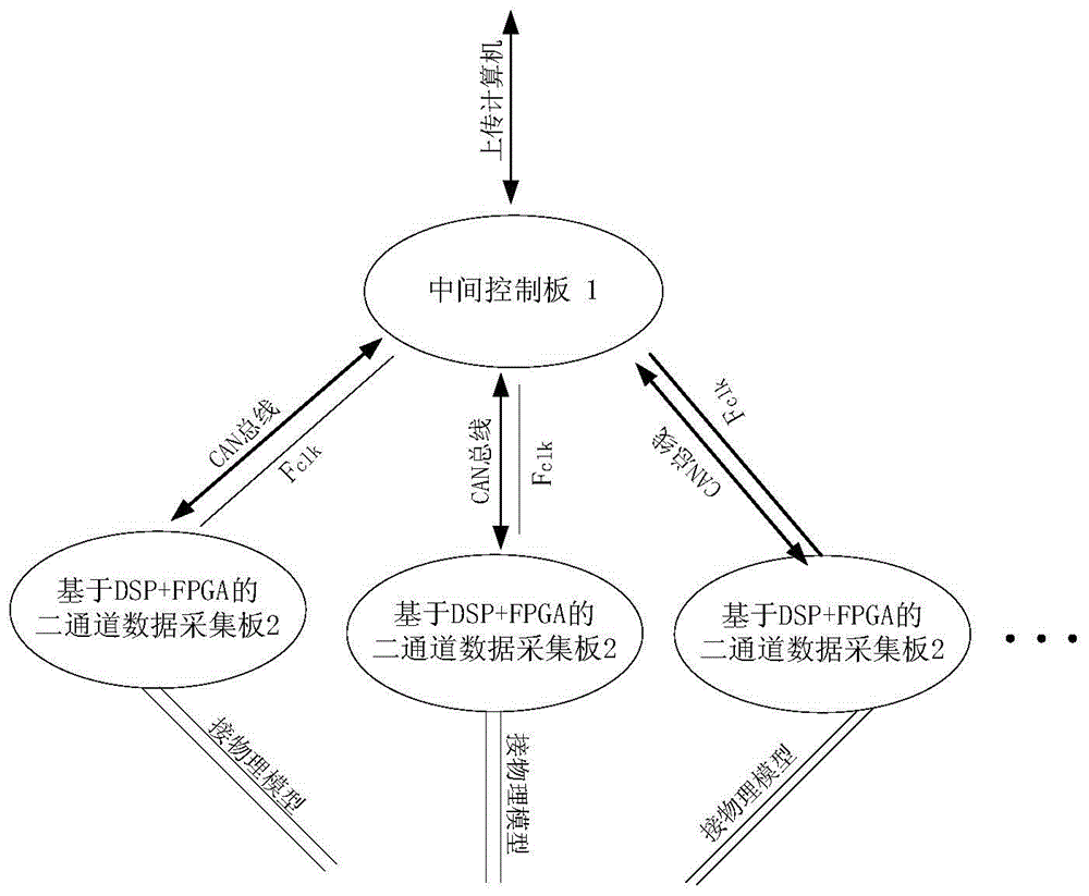
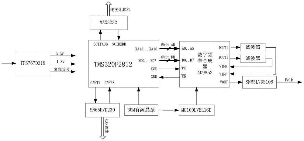
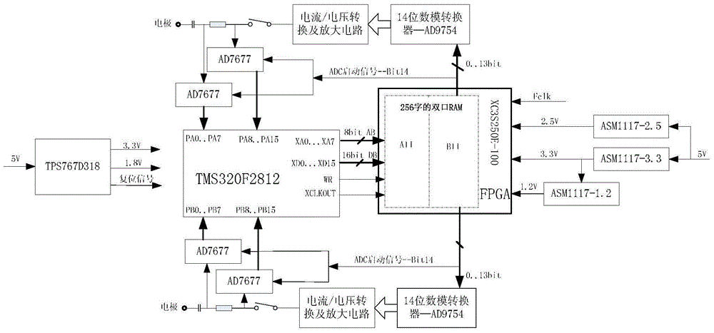
[0013] The hardware circuit system of the bioelectrical impedance imaging system based on the CAN bus of the present invention is composed of an intermediate control board and a data acquisition board. The middle control board 1 uses a TMS320F2812 digital signal processor produced by Texas Instruments as the control core, and expands a MAX3232 externally, and uses a serial port to receive instructions from the host computer; uses a digital synthesizer AD9852 to generate a clock with a frequency range of 0-80MHz Signal. System block diagram as figure 1 As shown, the circuit schematic diagram of the middle control board 1 is shown in figure 2 As shown, the schematic diagram of the data acquisition board is shown in image 3 shown.

[0014] The data acquisition ...


PUM


Abstract

The invention provides a bioelectricity impedance imaging system hardware circuit system based on a CAN bus. The hardware circuit comprises a middle control plate and a plurality of data collecting plates. The middle control plate is connected to a computer through a serial port connecting cable and receives an instruction sent by the computer. The middle control plate is connected with the data collecting plates through the CAN bus and a shield cable, and a unified programmable clock signal output by the middle control plate is input to the data collecting plates. The DSP of the data collecting plates acquires data through external interruption to carry out digital phase-sensitive demodulation, and the demodulation result is sent to the middle control plate through the CAN bus and finally sent to the computer. The bioelectricity impedance imaging system hardware circuit system has the advantages that the sweep frequency range of system drive signals ranges from 10 KHz to 10 MHz, the bioelectricity impedance imaging system hardware circuit system can be used as a flexible signal generator through the field programmability of an FPGA and can also carry out real-time compensation for collected signals of various channels, the effect on effective signals is offset, and the real-time performance and reliability are ensured.

Description

technical field [0001] The invention relates to an electrical imaging technology, in particular to a frequency-sweeping hardware circuit system applied to bioelectrical impedance imaging. Background technique [0002] Electrical Impedance Tomography (EIT) is one of the hot research topics in biomedical engineering today. It is a new generation of non-invasive functional imaging technology that has emerged in the past 20 years after morphology and structure imaging. EIT is to apply a small alternating current or voltage signal to the measured object by means of the excitation electrode placed on the body surface, and at the same time detect the voltage or current signal on the tissue surface through the measuring electrode, and calculate the corresponding electrical impedance and its change from the measured signal , and then according to different application purposes, extract the electrical characteristic information of tissues or organs related to human physiological and ...

Claims


Application Information

Patent Timeline
Patent Type & Authority Patents(China)
IPC IPC(8): A61B5/053
CPCA61B5/053
Inventor 侯海岭王化祥陈晓艳
Owner TIANJIN UNIV
Why Eureka
Try Eureka