An entrained-flow gasifier with solidification of slag in swirl

A technology of gasifier and entrained flow bed, which is applied in the field of coal chemical industry, and can solve problems such as the difficulty of hanging slag on the water-cooled wall, unfavorable structure of the cooling spiral tube, and large investment

Active Publication Date: 2016-08-31
CHINA UNIV OF PETROLEUM (EAST CHINA)
View PDF7 Cites 0 Cited by
  • Summary
  • Abstract
  • Description
  • Claims
  • Application Information

AI Technical Summary

Problems solved by technology

In practical applications, the performance is far superior to other synthetic entrained-bed gasifiers, but there are still difficulties and uneven slag hanging on the water-cooled wall, and large pieces of slag are easily generated, which affects long-term safe operation. High consumption, large investment, weak centrifugal effect of swirling cooling gas to drive syngas to rotate, large gas volume, resulting in a substantial increase in waste heat boiler load, cooling spiral tube structure is not conducive to the arrangement of side nozzles, complex structure, high pressure shell material requirements, etc. Major defects and deficiencies have affected the promotion and application of entrained bed gasifiers for solid phase slagging

Method used


Image

  • An entrained-flow gasifier with solidification of slag in swirl

Examples


Embodiment Construction

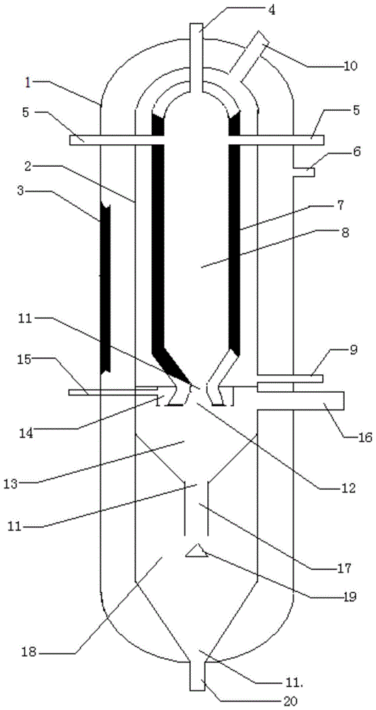
[0015] Below in conjunction with accompanying drawing, the present invention is described in detail: figure 1 As shown, a kind of entrained bed gasification furnace solidified by swirling liquid slag according to the present invention is composed of a gasification furnace pressure-resistant jacket 1, a high-pressure inert gas filling hole 6, a heat insulating material layer 3, a cooling jacket 2, a wear-resistant Material layer 7, top nozzle 4, side nozzle 5, gasification chamber 8, cooling water inlet 9, saturated steam outlet 10, segmented conical head 11, gasification product outlet 12, swirl cooling chamber 13, atomization Water cooling jacket 14, atomized water inlet 15, gas outlet 16, solidified slag discharge port 17, solid slag cooling chamber 18, anti-shock plate 19, water-cooled slag discharge port 20, characterized in that the gasifier is divided into gas The gasification furnace pressure jacket 1 and the gasifier liner, a gap of 50-500 mm is maintained between the ...


PUM


Abstract

The invention provides an entrained flow gasifier for swirling melt cinder solidification. The entrained flow gasifier is divided into a pressure resistant jacket and a gasifier liner, wherein a gasification chamber, a swirling cooling chamber and a cinder solidification cooling chamber form the gasifier liner and are respectively separated by virtue of segmenting conical sealing heads; a shell of the gasification chamber is sequentially provided with a thermal insulation material layer, a cooling jacket and a wear resistant material layer from outsides to insides; a cooling water inlet is formed in the bottom of the gasification chamber, and a saturated steam outlet is formed in the side surface of the top part of the gasification chamber; a top nozzle is formed in the center of the top part of the gasification chamber, and more than 3 side nozzles are uniformly formed in the upper part of the gasification chamber along the circumference; a gasification product discharge hole is formed in the center of the segmenting conical sealing head which is arranged at the bottom of the gasification chamber; an atomization water cooling sleeve is arranged at the outer side of a gasification product discharge hole in the swirling cooling chamber, and a gas outlet is formed in the upper part of the swirling cooling chamber; a solidified cinder discharge hole is formed in the center of the segmenting conical sealing head arranged at the bottom of the cooling chamber, is connected with the solidified cinder cooling chamber and is introduced into the middle of the solidified cinder cooling chamber, and a water cooling cinder discharge hole is formed in the center of the segmenting conical sealing head arranged at the bottom of the solidified cinder cooling chamber. With the adoption of the entrained flow gasifier for swirling melt cinder solidification, waste heat is fully utilized, and the difficulty of black water is eliminated.

Description

1. Technical field [0001] The invention relates to the field of coal chemical industry, in particular, to gasification of gas flow bed. 2. Background technology [0002] Coal gasification is the leading and key technology for the clean and efficient utilization of coal. Entrained bed gasification is a new coal co-current gasification technology developed in recent decades. The gasification agent and coal powder or coal slurry enter the gasification chamber through the nozzle, and the pyrolysis, combustion and gasification reactions of coal proceed almost simultaneously. , The high temperature ensures efficient coal gasification, and the minerals in the coal leave the gasifier after becoming slag. Compared with other gasification technologies, the pressurized entrained entrained bed gasification temperature is high, the processing capacity is large, the gas active components are high, and the gasification efficiency is high, which is the development direction of the coal syn...

Claims


Application Information

Patent Timeline
Patent Type & Authority Patents(China)
IPC IPC(8): C10J3/56
CPCY02P20/129
Inventor 田原宇乔英云田斌安晓熙
Owner CHINA UNIV OF PETROLEUM (EAST CHINA)
Why Eureka
Try Eureka