Vertical shaft working face ahead pre-grouting method

A working face and pre-grouting technology, which is applied in shaft equipment, sinking, earthwork drilling, etc., can solve the problems of poor construction quality of grout pads, long auxiliary time, and small number of drilling holes, and reduce the construction period of shafts , Reduce operating costs and speed up drilling

Active Publication Date: 2015-03-25
YUXI DAHONGSHAN MINING
View PDF5 Cites 36 Cited by
  • Summary
  • Abstract
  • Description
  • Claims
  • Application Information

AI Technical Summary

Problems solved by technology

[0004] The existing pre-grouting construction of the vertical shaft working face mostly has technical problems such as long construction period, poor water blocking effect and poor safety of the supported shaft wall for the bedrock aquifer with high-angle fractures
The pre-grouting period is long, mainly due to low drilling and injection efficiency and long auxiliary time
The main reasons for the poor water blocking effect are: firstly, the construction quality of the grout stop pad is poor, it is not resistant to high pressure, and it is easy to leak grout during grouting; The water is still gushing during construction; the third is that the drilling is shallow, and the aquifer blocked by one grouting is less; the fourth is that the grouting pressure is low, the grout diffusion range is sma

Method used


Image

  • Vertical shaft working face ahead pre-grouting method
  • Vertical shaft working face ahead pre-grouting method

Examples


Embodiment 1

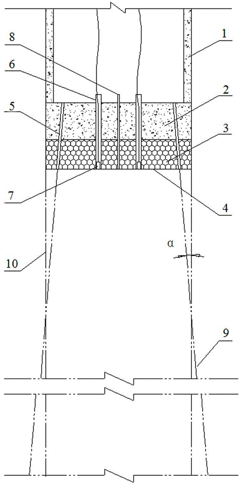
[0047]The return air shaft of the 1 million t / a mining project of the Erdaohe iron ore section of Dahongshan Iron Mine of Kunming Iron and Steel Co., Ltd., the wellhead elevation is 628.3m, the shaft section is circular, the net diameter is φ5.5m, the excavation diameter is φ6.2m, and the shaft neck section The excavation diameter is φ6.5~7.1m, and the depth of the well neck section is 42m. The working face revealed that the rock joints and fissures were developed, the rock was relatively broken, and water gushed out in many places on the working face. When the wellbore was excavated to an elevation of 603.1m (25.2m below the wellhead), the on-site measurement of the wellbore water inflow was 34.57m 3 / h.

[0048] According to the above geological conditions, after repeated analysis, comparison and deliberation, the height of the grouting water blocking section is 40m.

[0049] (1) Grouting parameter design

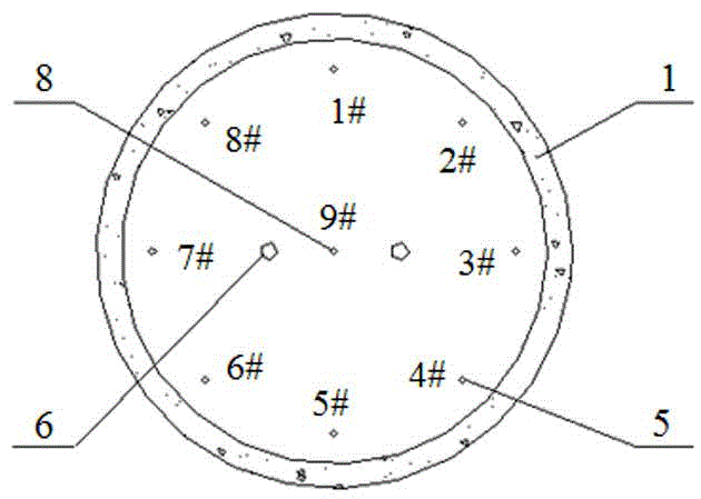
[0050] 1. Number of grouting holes

[0051] According to the abov...


PUM


Abstract

The invention discloses a vertical shaft working face ahead pre-grouting method which comprises the steps that a thick liquid stopping pad construction is carried out, wherein after a vertical shaft driving working face reaches a thick liquid stopping pad position, a grouting hole opening pipe, a checking hole opening pipe and a water filtering pipe are arranged according to the position and the dipping angle, a water filtering layer is paved, and then concrete placing is carried out; wall-back grouting is carried out, wherein back-wall cement thick liquid injection is carried out on the shaft wall of a supported vertical shaft; and pre-grouting is carried out, wherein after the steps are carried out, hole drilling is carried out from the buried the grouting hole opening pipe until water inflow amount exceeds preset amount, at the time, drilling is stopped, thick liquid is injected, after thick liquid is subjected to final setting, hole cleaning is carried out until water inflow amount exceeds the preset amount, then drilling stopping is carried out, thick liquid in injected until water inflow amount is smaller than the preset amount, then hole drilling is carried out continuously, the steps are carried out repeatedly, subsection-down type hole drilling grouting is carried out, and hole cleaning is carried out to the full depth. A pre-burying grouting hole opening pipe and shaft wall back-wall grouting are combined, working face drilling hole grouting is carried out through the grouting hole opening pipe, full blocking of a water inflow working face developed from a vertical shaft rock joint fissure is achieved, and the advantages of a short working period and good water blocking effect are achieved.

Description

technical field [0001] The invention belongs to the technical field of mine construction, and in particular relates to an advanced pre-grouting method for a shaft working face with short construction period, good water blocking effect and safe shaft construction. Background technique [0002] Grouting is to inject grout into the pores, cracks or cavities of rock and soil. The grout is diffused, solidified and hardened to reduce the permeability of rock and soil, increase its strength and stability, and achieve the purpose of rock and soil reinforcement and water blocking. It can not only be used for "dry well drilling" construction in order to reduce water gushing in the wellbore, speed up the drilling speed, and pre-grout all aquifers within the full depth of the wellbore, but also block water in fractured water-bearing strata and loose sandy soil layers. reinforcement. Grouting is one of the main methods of sinking wells and water control in mine construction, and it is a...

Claims


Application Information

Patent Timeline
IPC IPC(8): E21D5/04
CPCE21D1/16
Inventor 郭军包继锋李雪民董越权杨国永胡艳芳
Owner YUXI DAHONGSHAN MINING
Why Eureka
Try Eureka