Variable Capacity Vane Pump

A vane pump, capacity technology, applied in rotary piston pumps, pumps, pump components, etc., can solve problems such as pressure rise, achieve the effect of smooth compression speed and suppress shock pressure

Inactive Publication Date: 2018-04-06
HITACHI AUTOMOTIVE SYST STEERING
View PDF7 Cites 0 Cited by
  • Summary
  • Abstract
  • Description
  • Claims
  • Application Information

AI Technical Summary

Problems solved by technology

[0004] In the above-mentioned conventional devices, the pressure in the pump chamber rises sharply during low-speed rotation, and there is a need to further suppress the so-called shock pressure.

Method used


Image

  • Variable Capacity Vane Pump
  • Variable Capacity Vane Pump
  • Variable Capacity Vane Pump

Examples


Embodiment 1

[0062] [Structure of Variable Capacity Vane Pump]

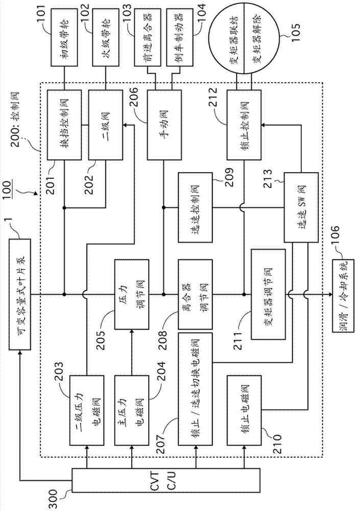
[0063] figure 1 It is a block diagram showing an example of a belt-type continuously variable transmission (CVT) 100 to which the variable displacement vane pump (hereinafter referred to as "vane pump") 1 of Embodiment 1 is applied. The outline of the vane pump (hereinafter referred to as "vane pump") 1 will be described. Vane pump 1 is used as a hydraulic pressure supply source for CVT 100 .

[0064] The vane pump 1 is driven by a crankshaft (not shown) of an internal combustion engine (engine), and sucks in / discharges a working fluid. Hydraulic oil, specifically, ATF (Automatic Transmission Fluid) is used as the working fluid. Hydraulic fluid (ATF) has a large elastic coefficient and a property in which the pressure changes greatly with a small change in volume.

[0065] In the control valve 200, various valves 201 to 213 controlled by the CVT control unit 300 are provided. The hydraulic oil discharged from the vane pu...

Embodiment 2

[0214] Figure 10 It is a graph showing the rate of change of the cam profile radius with respect to the angle for defining the stator profile when the stator eccentricity in Example 2 is the smallest.

[0215] In Example 2, such as Figure 10 As shown, the stator 8 differs from the first embodiment in that the rate of change of the cam profile radius has a negative value at the point where the stator profile definition angle is 180 degrees when the eccentricity δ of the stator 8 is the smallest.

[0216] The action of Example 2 will be described.

[0217] In the case where the stator 8 is formed such that when the stator eccentricity is the largest, the cam profile radius change rate temporarily decreases on the second confinement area side and then increases again, the smaller the eccentricity δ, the more the compression rate on the second confinement area side is suppressed or The larger the expansion ratio, the weaker the compression during high-speed rotation, and it may ...

Embodiment 3

[0223] Figure 11 It is a graph showing the change rate of the cam profile radius with respect to the angle for defining the stator profile when the stator eccentricity amount is maximum in Example 3.

[0224] In Example 3, such as Figure 11 As shown, the stator 8 is formed such that when the eccentric amount δ of the stator 8 is the largest, the maximum value when the cam profile radius change rate increases again after a temporary decrease is a negative value on the side of the second confinement area. 2 different.

[0225] The action of Example 3 will be described.

[0226] The greater the maximum value of the cam profile radius change rate when the cam profile radius change rate increases again, the larger the expansion rate is when the eccentricity δ is small. Therefore, in Example 3, by setting the cam profile radius change rate at which the maximum value is a negative value, it is possible to suppress Expansion with a small eccentricity δ can suppress cavitation dur...


PUM


Abstract

The present invention provides a variable displacement vane pump capable of suppressing shock pressure during low-speed rotation. Between the end (D) of the discharge port (44) and the start (A) of the suction port (43) as the first confinement area, the end (B) of the suction port and the start (C) of the discharge port ) as the second confinement area, taking the circumferential middle point of the start end of the suction port and the end end of the discharge port as the reference point, intersecting the rotation axis (O) of the drive shaft (5) of the rotor (6) at right angles and When the line passing through the reference point is used as the reference line, the cam support surface (93) formed on the inner peripheral side of the pump member housing part is such that the shortest distance from the reference line becomes smaller from the second confinement area side to the first confinement area side Formed, the stator (8) is formed such that when the eccentric amount δ of the stator (8) is maximum, the rate of change of the cam profile radius increases again after temporarily decreasing on the side of the second confinement area.

Description

technical field [0001] The invention relates to a variable capacity vane pump. Background technique [0002] Conventionally, there is known a variable capacity vane pump in which vanes are accommodated in slits of a rotor so as to be able to move in and out, and the volume of a pump chamber formed between a stator inner peripheral surface, a rotor outer peripheral surface, and the vanes is varied. Patent Document 1 describes an example related to the technique described above. [0003] Patent Document 1: (Japanese) Unexamined Patent Publication No. 2012-87777 [0004] In the conventional apparatus described above, the pressure in the pump chamber rises rapidly during low-speed rotation, and there is a need to further suppress the so-called surge pressure. Contents of the invention [0005] An object of the present invention is to provide a variable displacement vane pump capable of suppressing shock pressure during low-speed rotation. [0006] In the variable capacity v...

Claims


Application Information

Patent Timeline
Patent Type & Authority Patents(China)
IPC IPC(8): F04C14/22
CPCF04C14/226F01C21/0863F01C21/108F04C2/344F04C2/3442F04C2/3446F04C14/223F04C14/26F04C15/06F04C2240/811
Inventor 熊坂悟多饭岛正昭内田由纪雄村松聪
Owner HITACHI AUTOMOTIVE SYST STEERING
Why Eureka
Try Eureka