Carrying platform elevating gear, reaction cavity, and plasma processing device

A lifting device and reaction chamber technology, which is applied in ion implantation plating, metal material coating process, semiconductor/solid-state device manufacturing, etc. Problems such as adverse effects of process results, to achieve the effect of improving process uniformity, improving stability and accuracy, and reducing processing costs

Active Publication Date: 2015-03-25
BEIJING NAURA MICROELECTRONICS EQUIP CO LTD
View PDF3 Cites 24 Cited by
  • Summary
  • Abstract
  • Description
  • Claims
  • Application Information

AI Technical Summary

Problems solved by technology

In order to ensure the levelness of the heater surface and avoid accumulative errors in the assembly process of the lifting mechanism, the shaft lifting bracket usually does not constrain the displacement freedom of the bellows shaft in its radial direction, but the problem with this is: the shaft The lifting bracket often cannot constrain the rotational freedom of the bellows shaft, and the bellows, because it is a flexible material, cannot constrain the rotational freedom of the bellows shaft, so the bellows shaft is prone to rotation and drives the heater to deflect accordingly. This will not only cause the thimble to perform normal lifting and linear motion because it cannot pass through the heater, but also cause the workpiece placed on the heater to deviate relative to the upper surface of the heater, thus bringing bad process results influences

Method used


Image

  • Carrying platform elevating gear, reaction cavity, and plasma processing device
  • Carrying platform elevating gear, reaction cavity, and plasma processing device
  • Carrying platform elevating gear, reaction cavity, and plasma processing device

Examples


Embodiment Construction

[0028] In order to enable those skilled in the art to better understand the technical solutions of the present invention, the present invention will be described in detail below in conjunction with the accompanying drawings.

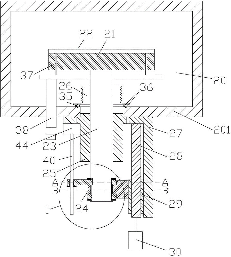
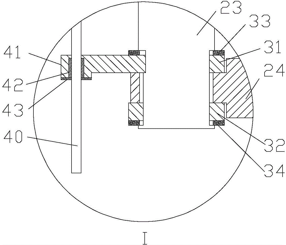
[0029] Figure 2A It is a cross-sectional view of a platform lifting device provided by an embodiment of the present invention. Figure 2B for Figure 2A Partial enlarged view of the middle I region. Figure 2C for Figure 2A A cross-sectional view of the central axis lifting bracket along line A-A. Figure 2C for Figure 2A A cross-sectional view of the central axis lifting bracket along line A-A. Figure 2D for Figure 2AThe sectional view of the central axis lifting bracket along the line B-B. Please also refer to Figure 2A , Figure 2B , Figure 2C and Figure 2D , the platform lifting device includes a lifting unit, which includes a bellows shaft 23, a shaft lifting bracket 24, a linear bearing 25 and a bracket driving source. Wherein, ...


PUM


Abstract

The invention provides a carrying platform elevating gear, a reaction cavity, and a plasma processing device. A bracket driving source drives a shaft lifting bracket to do lifting motion. A bellows shaft passes through the shaft lifting bracket and is fixedly connected with the shaft lifting bracket, so as to do lifting motion with the shaft lifting bracket in a linear bearing, thereby realizing lifting motion of the carrying platform which is fixed on the bellows shaft. In the carrying platform elevating gear, a guiding mechanism is used to limit axial rotation of the bellows shaft in a lifting process. The bellows shaft passes through the linear bearing, a guiding shaft installing assembly, and a shaft lifting bracket in sequence. The guiding shaft installing assembly tightly holds the bellows shaft. The upper end of the guiding shaft is fixed on the cavity wall of the reaction cavity. The lower end of the guiding shaft passes through the guiding shaft installing assembly, so that the guiding shaft installing assembly does lifting motion with the shaft lifting bracket along the guiding shaft. The carrying platform elevating gear can limit rotation degree of freedom of a connecting rod, so as to ensure a carrying device from deflecting.

Description

technical field [0001] The invention relates to the technical field of microelectronic processing, in particular to a platform lifting device, a reaction chamber and plasma processing equipment. Background technique [0002] In the process of manufacturing integrated circuits (IC) and microelectromechanical systems (MEMS), especially in the process of implementing plasma etching (ETCH), physical vapor deposition (PVD), chemical vapor deposition (CVD), etc., often A heater is used to heat workpieces such as wafers. Moreover, the heater is usually driven by the lifting mechanism to perform a lifting linear motion, so as to cooperate with the manipulator to realize the pick-and-place of the processed workpiece, and to adjust the distance between the processed workpiece and the target. In order to ensure the uniformity of the process, it is necessary to ensure the levelness of the heater surface. [0003] figure 1 It is a sectional view of an existing plasma processing equipm...

Claims


Application Information

Patent Timeline
Patent Type & Authority Applications(China)
IPC IPC(8): H01L21/67C23C14/50C23C16/458
CPCH01J37/20H01L21/68742
Inventor 吕峰张风港
Owner BEIJING NAURA MICROELECTRONICS EQUIP CO LTD
Why Eureka
Try Eureka