
Array substrate, display device, and method for manufacturing array substrate

A technology of an array substrate and a manufacturing method, which is applied in the field of thin-film transistor liquid crystal display, and can solve problems such as poor bonding and affecting bonding effects

Active Publication Date: 2017-05-10
BOE TECH GRP CO LTD +1
View PDF3 Cites 0 Cited by
  • Summary
  • Abstract
  • Description
  • Claims
  • Application Information

AI Technical Summary

Problems solved by technology

The etchant of Mo metal can corrode IZO metal, so when preparing the array substrate of the above-mentioned ADS structure, when etching the source-drain metal electrode layer, the first layer of IZO forming the pixel electrode 4 will be corroded at the same time, which greatly affects the second layer. The overlapping effect of one layer of IZO and the source and drain metal electrode layers causes poor lap connection between the first layer of IZO and the source and drain metal electrode layers

Method used


Image

  • Array substrate, display device, and method for manufacturing array substrate
  • Array substrate, display device, and method for manufacturing array substrate
  • Array substrate, display device, and method for manufacturing array substrate

Examples


Embodiment Construction

[0037] The present invention will be further described below in conjunction with the accompanying drawings and specific embodiments, so that those skilled in the art can better understand the present invention and implement it, but the examples given are not intended to limit the present invention.

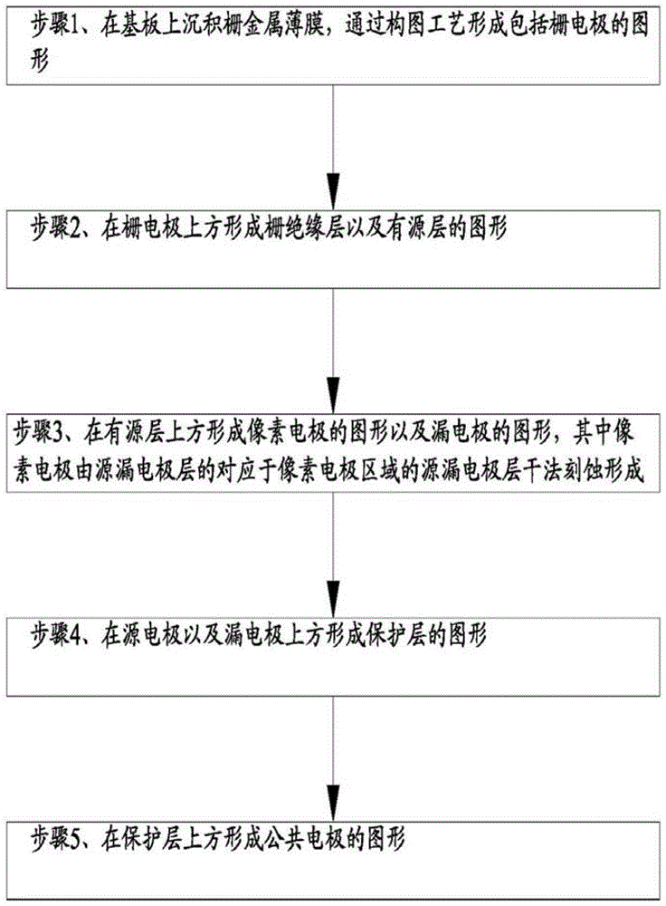
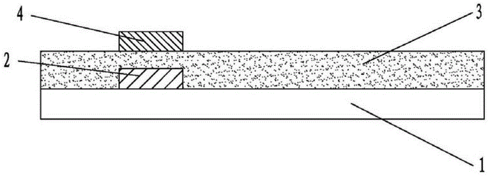
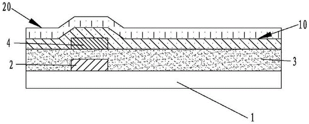
[0038] Such as figure 1 , figure 2 , image 3 , Figure 4 , Figure 5 , Image 6 as well as Figure 7 As shown, the embodiment of the manufacturing method of the array substrate of the present invention includes:

[0039] Step 1, depositing a gate metal thin film on the substrate 1, and forming a pattern including the gate electrode 2 through a patterning process;

[0040] Step 2, forming patterns of the gate insulating layer 3 and the active layer 4 above the gate electrode 2;

[0041] Step 3, forming the pattern of the pixel electrode 11 and the pattern of the drain electrode 22 on the active layer 4;

[0042] Step 4, forming a pattern of the protective layer 5 above t...


PUM


Abstract

The invention provides an array substrate, a display device and a manufacturing method of the array substrate. The manufacturing method of the array substrate includes the steps that a pixel electrode layer and a source and drain electrode layer are deposited; the portion, corresponding to a pixel electrode region, of the source and drain electrode layer is etched away according to a dry method, a pixel electrode is exposed, a source electrode and a drain electrode are formed, and the source electrode and the drain electrode are located above the pixel electrode. The array substrate comprises a gate insulation layer, the pixel electrode on an active layer, the source electrode and the drain electrode, wherein the source electrode and the drain electrode are formed above the pixel electrode. The pixel electrode is made of indium zinc oxide, the source electrode and the drain electrode are formed by etching the source and drain electrode layer, the portion, corresponding to the pixel electrode region, of the source and drain electrode layer is etched away according to the dry method, and therefore the pixel electrode is exposed. The display device comprises the array substrate. By the adoption of the technical scheme, the pixel electrode is located below the source electrode and the drain electrode, the portion, corresponding to the pixel electrode region, of the source and drain electrode layer is etched away according to the dry method, and it is guaranteed that the pixel electrode layer is not corroded.

Description

technical field [0001] The invention relates to the technical field of thin film transistor liquid crystal display, in particular to an array substrate, a display device and a manufacturing method of the array substrate. Background technique [0002] ADS is the abbreviation of ADSDS (ADvanced Super Dimension Switch), that is, advanced super-dimensional field switching technology, through the electric field generated by the edge of the slit electrode in the same plane and the electric field generated between the slit electrode layer and the plate electrode layer to form a multi-dimensional electric field, All oriented liquid crystal molecules between the slit electrodes in the liquid crystal cell and directly above the electrodes can be rotated, thereby improving the working efficiency of the liquid crystal and increasing the light transmission efficiency. [0003] Generally, the array substrate of an ADS mode thin-film transistor liquid crystal display includes a substrate, ...

Claims


Application Information

Patent Timeline
Patent Type & Authority Patents(China)
IPC IPC(8): H01L21/77G02F1/1362G02F1/1368H01L27/12
Inventor 郭建
Owner BOE TECH GRP CO LTD
Learn More