Multi-channel signal output circuit

A signal output, multi-channel technology, applied in the radio frequency field, can solve the problems of cumbersome operation and high cost of multi-channel radio frequency signal circuits, and achieve the effect of improving adjustment efficiency

Inactive Publication Date: 2015-03-25
SHANGHAI UNITED IMAGING HEALTHCARE
View PDF5 Cites 4 Cited by
  • Summary
  • Abstract
  • Description
  • Claims
  • Application Information

AI Technical Summary

Problems solved by technology

[0005] The present invention solves the problem of high cost and cumbersome operation of the supply circuit of multiple radio frequency signals in the prior art

Method used


Image

  • Multi-channel signal output circuit
  • Multi-channel signal output circuit
  • Multi-channel signal output circuit

Examples


Embodiment 1

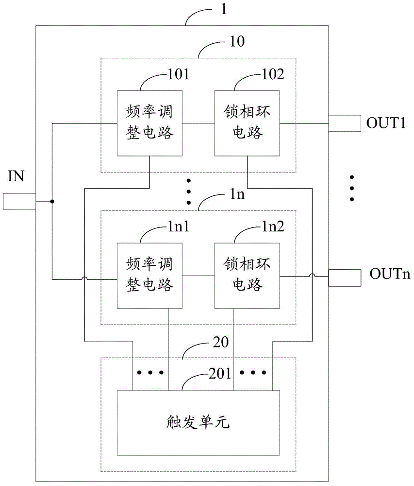
[0042] figure 1 A schematic structural diagram of Embodiment 1 of the multi-channel signal output circuit of the present invention is shown. refer to figure 1 , the multi-channel signal output circuit 1 includes: a radio frequency signal input terminal IN; at least one adjustment circuit, such as figure 1 The first adjustment circuit 10 shown in ..., the nth adjustment circuit 1n; the logic control circuit 20; at least one radio frequency signal output terminal, such as figure 1 The first radio frequency signal output terminal OUT1, ..., the nth radio frequency signal output terminal OUTn shown in. in,

[0043] The radio frequency signal input terminal IN is suitable for receiving a first radio frequency signal;

[0044] Each adjustment circuit includes: a frequency adjustment circuit and a phase locked loop circuit (Phase Locked Loop, PLL); the logic control circuit 20 includes a trigger unit 201, and the trigger unit 201 is adapted to generate Trigger signal for phase l...

Embodiment 2

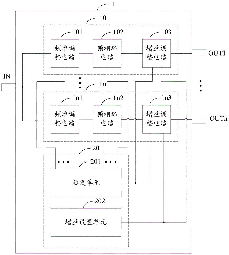
[0056] figure 2 A schematic structural diagram of Embodiment 2 of the multi-channel signal output circuit of the present invention is shown. refer to figure 2 , compared with Embodiment 1, the difference of this embodiment is that: each adjustment circuit also includes a gain adjustment circuit connected to the phase-locked loop circuit; Adjustment, the second radio frequency signal output by the radio frequency signal output end is the adjustment signal after the power adjustment; the trigger unit 201 in the logic control circuit 20 is also adapted to generate a trigger signal corresponding to the gain adjustment circuit, each The gain adjustment circuit starts to work after receiving the trigger signal output by the trigger unit 201, which will not be repeated here; the logic control circuit 20 also includes a gain setting unit 202, and the gain setting unit 202 is adapted to output a gain coefficient to the gain adjustment circuit.

[0057] refer to figure 2 , the fi...

Embodiment 3

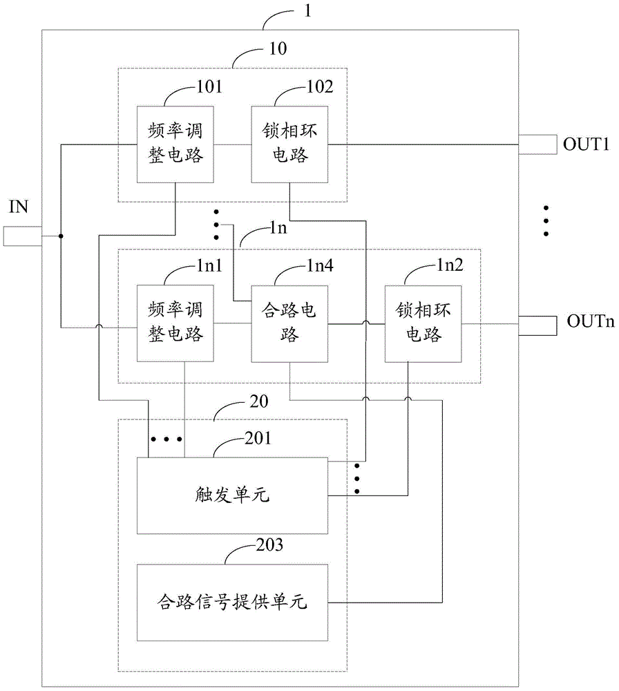
[0061] Compared with Embodiment 1, in this embodiment, the adjustment circuit may further include: a combination circuit connected to at least one phase-locked loop circuit and at least two frequency adjustment circuits, and the combination circuit is suitable for combining Under the control of the signal, the adjustment signals output by the correspondingly connected at least two frequency adjustment circuits are combined and the combined adjustment signal is output to the correspondingly connected at least one phase-locked loop circuit.

[0062] Correspondingly, the logic control circuit 20 further includes: a combining signal providing unit connected to the combining circuit, and the combining signal providing unit is adapted to provide the combining signal.

[0063] Specifically, refer to image 3 , the nth adjustment circuit includes a combination circuit 1n4, and the combination circuit 1n4 is connected with the frequency adjustment circuit 1n1 in the nth adjustment circ...


PUM


Abstract

A multi-channel signal output circuit comprises a radio frequency signal input end, at least one adjustment circuit, at least one radio frequency signal output end, and a logic control circuit. The radio frequency signal input end is suitable for receiving a first radio frequency signal. Each adjustment circuit comprises a frequency adjustment circuit and a phase-locked loop, wherein the frequency adjustment circuit is suitable for acquiring an adjustment signal based on the first radio frequency signal, the frequency of the adjustment signal is a first frequency threshold, and the phase-locked loop is suitable for locking the frequency of the adjustment signal when the frequency of the adjustment signal is greater than or equal to a second frequency threshold. The radio frequency signal output ends and the adjustment circuits are connected in a one-to-one correspondence manner, and each radio frequency signal output end is suitable for outputting a second radio frequency signal relevant to the frequency-locked adjustment signal. The logic control circuit comprises a trigger unit suitable for generating trigger signals at least corresponding to the frequency adjustment circuits and the phase-locked loops. By adopting the multi-channel signal output circuit of the invention, the cost is reduced, and the efficiency of signal adjustment is increased.

Description

technical field [0001] The invention relates to the field of radio frequency technology, in particular to a multi-channel signal output circuit. Background technique [0002] Radio frequency signals are used more and more frequently in fields such as communication, electronics, radar and medical treatment. For example, in the magnetic resonance system, the magnetic resonance system passes through an excitation signal, usually a pulse sequence (such as a square wave or a sine wave). This pulse sequence first passes through a 1.14MHz mixer, and then passes through the LO local oscillator (frequency 65MHz ) for quadrature modulation, thus generating the radio frequency excitation signal of the magnetic resonance system (frequency 65MHz-1.14MHz=63.86mHz), the radio frequency excitation signal with a frequency of 63.86MHz resonates with the hydrogen atoms of the human body in the magnetic field, The resonance of hydrogen atoms will spin and shift. After the excitation of radio f...

Claims


Application Information

Patent Timeline
Patent Type & Authority Applications(China)
IPC IPC(8): H03L7/08H03L7/16
Inventor 封勇福王木林
Owner SHANGHAI UNITED IMAGING HEALTHCARE
Why Eureka
Try Eureka