Power grid equipment state information cloud storage system and data uploading and downloading methods thereof

A technology of cloud storage system and state information, applied in transmission system, redundant data error detection in computing, electrical components, etc., can solve problems such as poor scalability, difficult data state evaluation and diagnosis and maintenance, and high platform load

Inactive Publication Date: 2015-03-25
国网甘肃省电力公司信息通信公司
View PDF5 Cites 14 Cited by
  • Summary
  • Abstract
  • Description
  • Claims
  • Application Information

AI Technical Summary

Problems solved by technology

[0003] (1) All kinds of information systems are in the stage of decentralized processing and are independent of the computer monitoring system. These systems lack system information sharing and become different information islands. Multiple different status systems need to be maintained separately. Repeated configuration of various devices leads to waste of resources ;
[0004] (2) The communication modules and data information interfaces of each system are not unified, mainly between each substation and control center, and between each system, making it difficult to integrate various data for status assessment and diagnosis and maintenance;
[0005] (3) Most of the data sources of the system currently under construction are obtained from existing business systems in power companies. Expensive large-scale cloud storage servers are used to build basic configurations, and disk arrays are used to realize hardware storage. The software completes tightly coupled business applications, so the system cost is high and the scalability is poor;
[0006] (4) There is a bottleneck in the input and output access requirements. Massive time series data and high concurrent read and write requirements for the data platform make the load on the platform very high. It is difficult for the traditional database to meet the requirements of the smart grid.

Method used


Image

  • Power grid equipment state information cloud storage system and data uploading and downloading methods thereof
  • Power grid equipment state information cloud storage system and data uploading and downloading methods thereof
  • Power grid equipment state information cloud storage system and data uploading and downloading methods thereof

Examples


Embodiment Construction

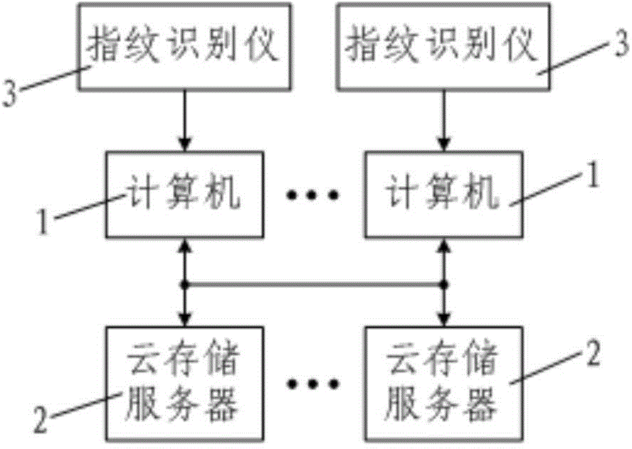
[0089] Such as figure 1 As shown, the grid equipment state information cloud storage system of the present invention includes a plurality of computers 1 arranged in each substation as client devices and a cloud storage server cluster arranged in the center of the smart grid as cloud storage end devices. The computer 1 and each cloud storage server 2 in the cloud storage server cluster are connected and communicate with each other through the Internet network, and a plurality of the computers 1 are connected with a fingerprint recognition device 3 .

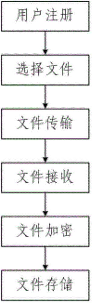
[0090] Such as figure 2 As shown, the data upload method of the grid equipment state information cloud storage system of the present invention includes the following steps:

[0091] Step 1, user registration: the user inputs fingerprint information through the fingerprint recognition device 3, and the computer 1 connected to the fingerprint recognition device 3 reads the fingerprint information and extracts the user fingerprint ...


PUM


Abstract

The invention discloses a power grid equipment state information cloud storage system which comprises a plurality of computers and a cloud storage server cluster, wherein the computers are connected through the Internet and are arranged in all transformer substations to serve as client equipment, the cloud storage server cluster is arranged at an intelligent power grid center to serve as cloud storage end equipment, and all the computers are connected with fingerprint identification instruments. The invention further discloses a data uploading method of the power grid equipment state information cloud storage system. The uploading method includes the steps of (1) user registration, (2) file selection, (3) file transmission, (4) file receiving, (5) file encryption and (6) file storage. The invention further discloses a data downloading method of the power grid equipment state information cloud storage system. The downloading method includes the steps of (1) user certification, (2) file selection, (3) threshold restricting, (4) file decryption, (5) file transmission and (6) file receiving. By means of the power grid equipment state information cloud storage system and the data uploading and downloading methods of the power grid equipment state information cloud storage system, power grid information safety is improved, the integrity of the downloaded files is guaranteed, and the utilization rate of power grid information is increased.

Description

technical field [0001] The invention belongs to the technical field of grid information storage, and in particular relates to a cloud storage system for grid equipment status information and a data upload and download method thereof. Background technique [0002] The grid information storage in the prior art has the following defects: [0003] (1) All kinds of information systems are in the decentralized processing stage and are independent of the computer monitoring system. These systems lack system information sharing and become different information islands. Multiple different status systems need to be maintained separately. The repeated configuration of various devices leads to waste of resources ; [0004] (2) The communication modules and data information interfaces of each system are not unified, mainly appearing between each substation and control center, as well as between each system, and it is difficult to integrate various data for status assessment and diagnosi...

Claims


Application Information

Patent Timeline
Patent Type & Authority Applications(China)
IPC IPC(8): H04L29/08H04L29/06
CPCH04L67/1097G06F11/14H04L63/0428H04L63/0861H04L67/06
Inventor 马志程杨鹏张旭张磊卫翔郑毅杨明杰刘少博王琼曹玮润
Owner 国网甘肃省电力公司信息通信公司
Why Eureka
Try Eureka